A ring can look redundant on a network drawing and still fail the production requirement. Pull one fiber, wait for the switch LEDs to settle, and connectivity may return. The PLC session may already have timed out, the drive may have entered a safe state, or several seconds of camera footage may be missing.
The protocol has not necessarily failed. The design may have compared protocol names without defining what the application could tolerate.
ERPS, or Ethernet Ring Protection Switching, is an ITU‑T G.8032 protocol designed to protect Ethernet ring networks by restoring traffic through an alternate path after a qualifying link or node failure. Unlike RSTP, which manages general bridged topologies, and MRP, which is commonly used in PROFINET-oriented industrial rings, ERPS is designed specifically for managed Ethernet ring protection.
RSTP, MRP, and ERPS can reconverge traffic to an alternate Layer 2 forwarding path under supported fault conditions. They do not use the same control model, fit the same topology, or provide the same level of predictability. Selecting among them requires more than choosing the smallest recovery-time number on a datasheet.
Quick answer:
- Choose RSTP when the network needs a broadly supported loop-prevention protocol across general bridged topologies and the application can accept topology- and implementation-dependent reconvergence.
- Choose MRP when the project calls for an IEC 62439-2 industrial ring, often within a PROFINET-oriented automation environment, and every participating ring device supports the required MRP role and recovery profile.
- Choose ERPS when the design uses a managed Ethernet ring or interconnected rings, commonly over fiber in transportation, energy, utility, or distributed infrastructure, and the selected switches implement the required ITU-T G.8032 functions.
- Choose none of the three as the sole protection method when the application requires seamless redundancy or cannot tolerate frame loss during reconfiguration. PRP, HSR, or IEEE 802.1CB FRER may need to be evaluated instead.
| Protocol | Defensible recovery statement | Important condition |
|---|---|---|
| RSTP | No universal guaranteed time | Depends on topology, timers and implementation |
| MRP | Planning target up to 200 ms | Common guidance assumes a compliant ring and typically up to 50 devices |
| ERPS | Some implementations target sub-50 ms | Must be verified against the exact model, ring size and configuration |
Selection rule: specify the maximum permissible application interruption first. Then choose the protocol, switches, firmware, topology, and test method that can demonstrate compliance.
Watch the video to quickly learn industrial Ethernet redundancy protocol difference:
What the Recovery-Time Numbers Do and Do Not Prove
The fastest useful answer is not a universal ranking. It is a statement of what can be defended from the governing guidance and what still needs device-level evidence.
| Protocol | Defensible screening statement | What the number does not prove |
|---|---|---|
| RSTP | There is no universal RSTP recovery time that applies to every topology and implementation. Test the exact network. | The word “rapid” does not guarantee that a PLC, drive, camera, or TCP session will recover within a particular deadline. |
| MRP | The PROFINET redundancy planning guideline states that MRP reconfiguration must not exceed 200 ms. Its planning example limits the ring to 50 devices to meet that target and tells users to follow manufacturer-specific limits, which may be lower. | The 200 ms reference does not prove a faster profile, a larger ring, or application recovery within 200 ms for an arbitrary combination of devices. |
| ERPS | ITU-T G.8032 defines Ethernet ring protection behavior, but the exact switching result must be verified for the selected switch, firmware, ring size, topology, traffic, timers, and failure mode. | An ERPS feature label alone does not prove a universal sub-50 ms result or identical behavior across products. |
Treat those statements as a qualification screen, not a commissioning certificate. Ask where a published number starts and stops: link-loss detection, protocol state change, restored frame delivery, recovered ping, or recovered application session.
A three-question shortlist
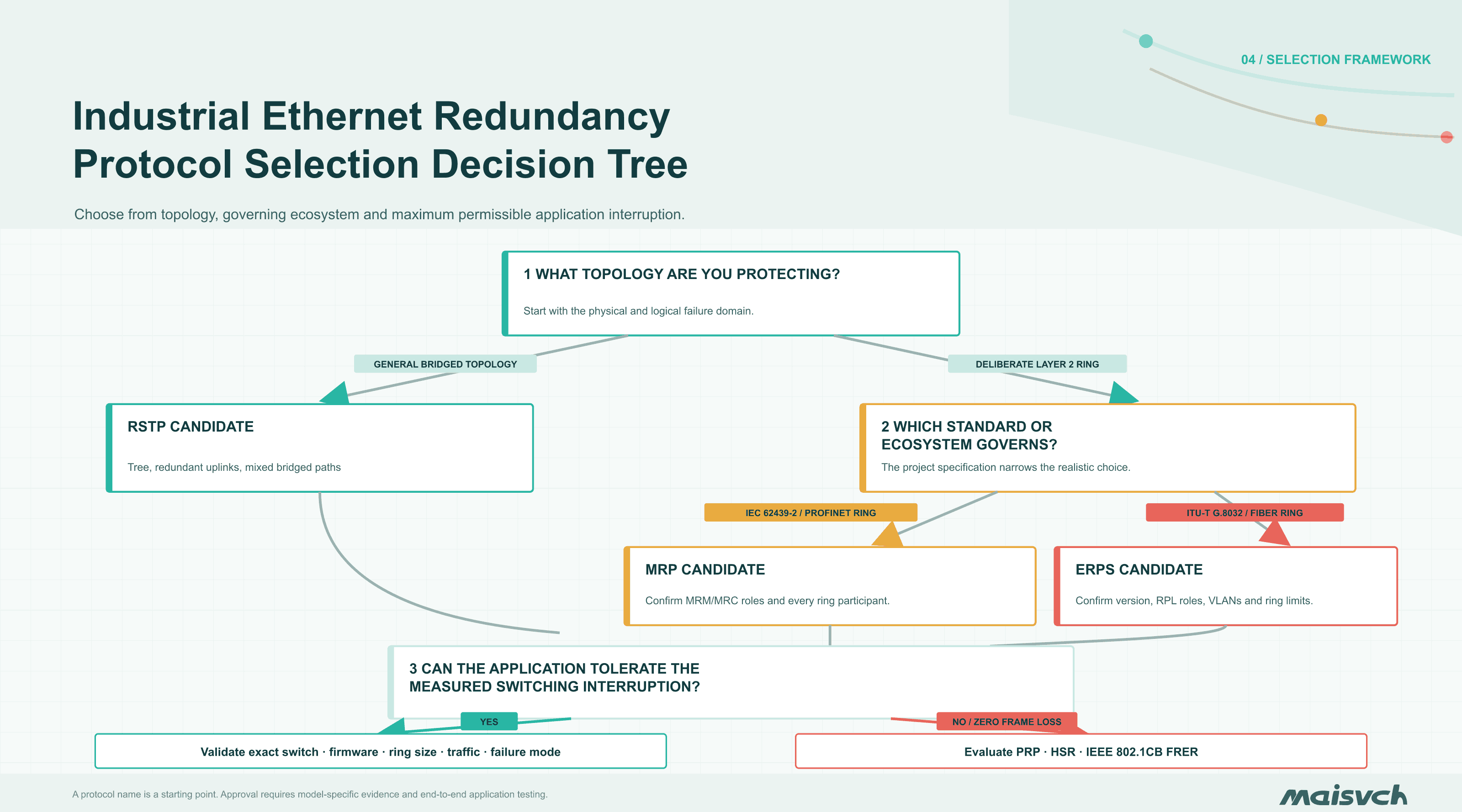
- What is the protected topology? General bridged topology points first to RSTP; a deliberately managed ring points first to MRP or ERPS.
- Which standard or ecosystem governs the project? An IEC 62439-2 or PROFINET ring requirement points toward MRP; a G.8032 ring requirement points toward ERPS.
- What is the maximum permissible application interruption? If no frame loss is acceptable, a reconfiguration protocol may be the wrong architecture even when its switching number looks fast.
Jump to: comparison table · RSTP · MRP · ERPS · decision framework · FAT testing · Maisvch product fit
Why a “50 ms Protocol” May Not Produce 50 ms Application Recovery
Protocol comparison pages often place three numbers in a table and declare the smallest number the winner. That shortcut hides the engineering question.
A more useful model is:
Application outage =
fault detection
+ protocol state change
+ forwarding-table update
+ endpoint or session recovery
Each term can change independently.
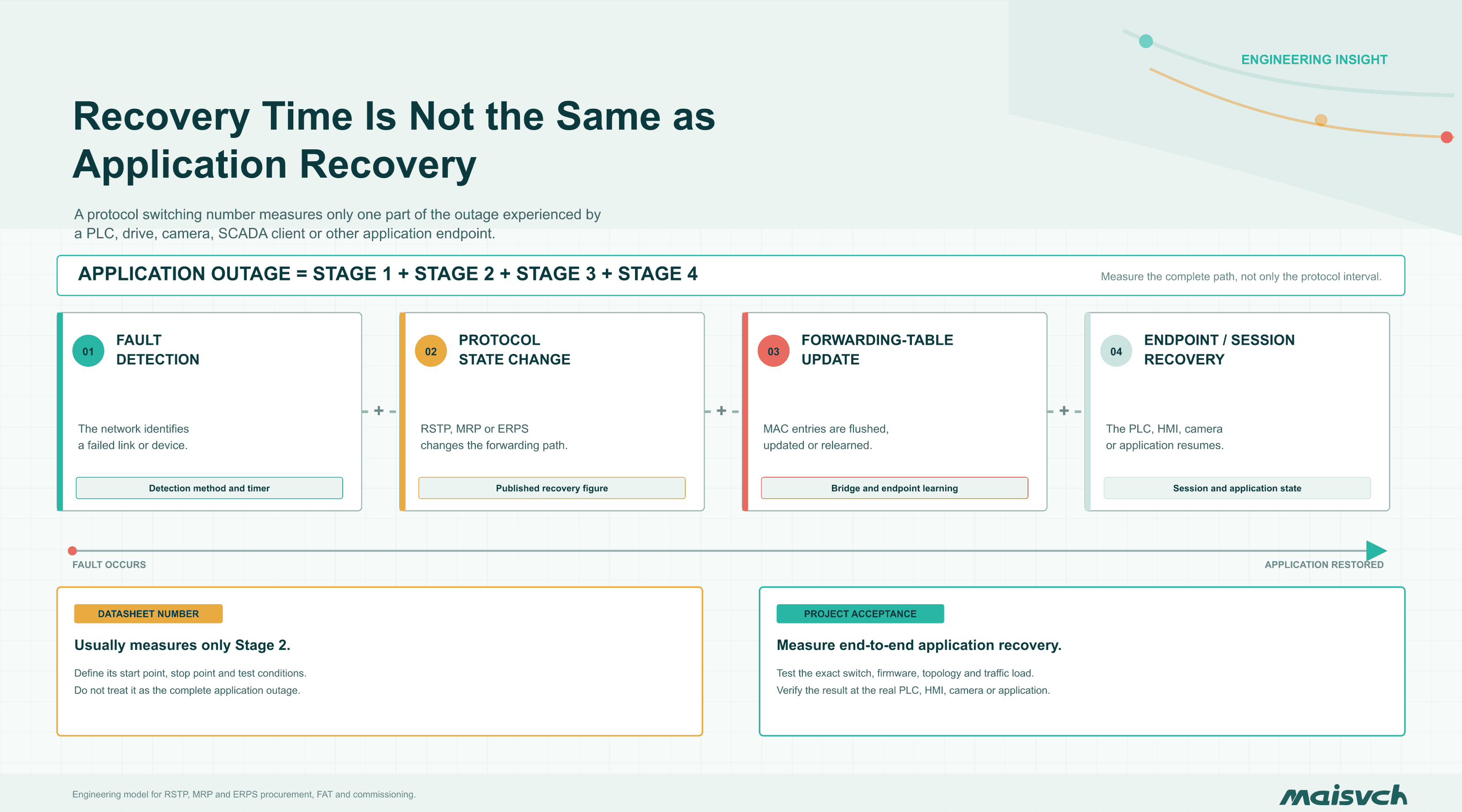
1. Fault detection
A pulled copper cable usually produces an immediate local link-down event. A remote switch freeze, unidirectional fiber fault, media-converter fault, or degraded optical signal may not. OAM, loss-of-signal behavior, and device diagnostics affect when the protocol is told that a failure exists.
2. Protocol state change
RSTP recalculates the active spanning tree. MRP changes the managed ring state. ERPS processes the protection event and changes the RPL-related forwarding state. This is the interval most datasheets describe, but the measurement start and end points are not always identical.
3. Forwarding-table update
After the path changes, switches may need to flush or relearn MAC address entries. Broadcast, multicast, and unknown-unicast traffic can behave differently during that transition. A ring that carries PROFINET, EtherNet/IP, IEC 61850, video, and engineering traffic should be tested with the real traffic mix.
4. Endpoint and application recovery
A PLC, HMI, drive, camera, SCADA client, or TCP session may have its own timeout and reconnect behavior. The network can be forwarding again while the application remains unavailable.
Procurement consequence: ask vendors to define what their recovery number measures, on what ring size, with which firmware, under which traffic conditions, and for which failure type.
First Separate the Physical Ring from the Redundancy Protocol
A physical Ethernet ring connects the last switch back to the first. If every port forwards normally, broadcast and unknown-unicast frames can circulate, multiply, and destabilize the Layer 2 network.
A redundancy protocol creates a loop-free logical topology on top of that physical ring. In the healthy state, one path is kept out of service or placed in a discarding state. When a qualifying fault occurs, the protocol changes the forwarding state so traffic can use the surviving path.
That leads to three distinctions that should appear in every design specification:
- Physical topology: the cables, ports, switches, and device locations.
- Logical topology: the path that carries traffic during normal operation and after a fault.
- Recovery requirement: the longest interruption the application can accept, including packet loss and endpoint recovery.
RSTP, MRP, and ERPS are reconfiguration-based mechanisms. Frames already in transit can be lost while the active topology changes. A recovered ping therefore does not prove that control traffic remained inside its watchdog limit.
For a broader comparison of physical layouts, review the Maisvch guide to industrial Ethernet network topologies before selecting the ring protocol.
RSTP vs MRP vs ERPS at a Glance
| Decision factor | RSTP | MRP | ERPS |
|---|---|---|---|
| Full name | Rapid Spanning Tree Protocol | Media Redundancy Protocol | Ethernet Ring Protection Switching |
| Current standards reference | IEEE 802.1Q; historically introduced as IEEE 802.1w | IEC 62439-2:2021 | ITU-T G.8032/Y.1344 |
| Primary topology | General bridged networks, including tree, redundant star, mesh, and physical rings | Industrial Ethernet ring | Ethernet ring and supported ring-interconnection designs |
| Main control model | Root Bridge election and RSTP port roles | Media Redundancy Manager and Media Redundancy Clients | Ring Protection Link, RPL Owner/Neighbour roles, and R-APS messages |
| Healthy-state loop prevention | One or more ports remain outside the active spanning tree | The manager controls a blocked ring path | The Ring Protection Link is blocked for protected traffic |
| Published recovery-time reference | No universal application-level guarantee; topology- and implementation-dependent | PI planning guidance uses a maximum 200 ms MRP reconfiguration time | Verify the exact product claim and test conditions; the protocol name alone is insufficient |
| Ring-size statement | Determined by the validated topology, design and implementation | PI planning guidance uses up to 50 devices to comply with 200 ms and notes that manufacturer limits may be lower | Confirm the validated ring size, ERP instances and any ring-interconnection limits for the selected implementation |
| Recovery predictability | Depends strongly on topology, port state, configuration, and implementation | Designed for deterministic reaction to a specified single failure | Protection switching behavior is defined by G.8032; actual performance depends on the implementation and design |
| Common industrial fit | Plant distribution, mixed-vendor bridged networks, noncritical rings | Machine and automation rings, especially where IEC 62439-2 or PROFINET ecosystem support is required | Fiber backbones, railways, utilities, energy sites, smart-city and distributed infrastructure |
| Main strength | Broad support and topology flexibility | Industrial ring focus and defined management roles | Purpose-built Ethernet ring protection and support for more advanced ring architectures |
| Main risk | Treating “rapid” as a guaranteed application recovery time | Assuming any switch labeled “ring capable” supports the required MRP profile | Assuming every ERPS implementation supports the same version, instances, interconnection behavior, and performance |
The table identifies a starting point, not a winner. The switch model, ring size, link type, traffic load, control settings, firmware, and failure mode still determine the result.
How RSTP Works in an Industrial Ethernet Network
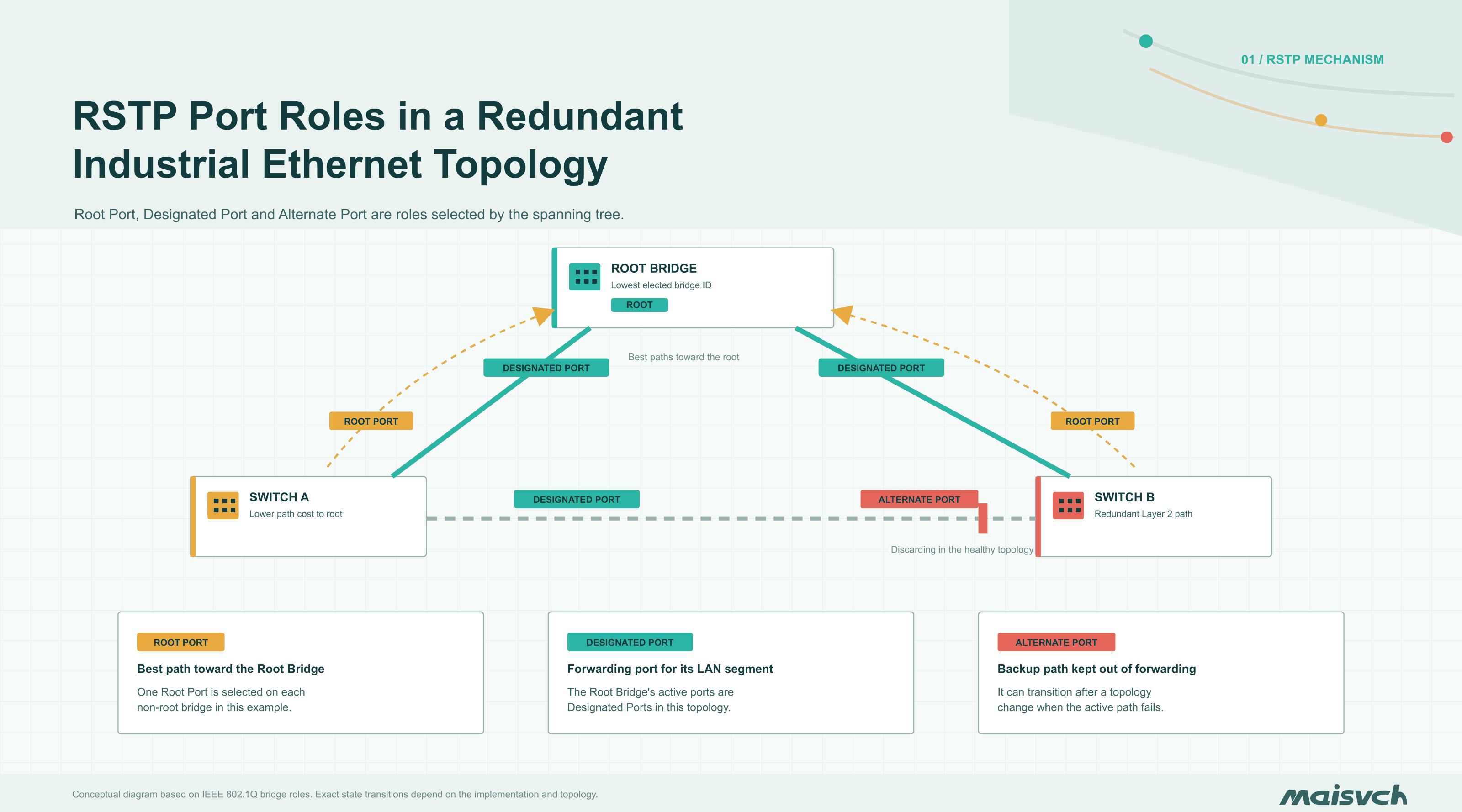
RSTP builds a loop-free active topology across Ethernet bridges. It elects a Root Bridge and assigns port roles according to path cost and bridge information exchanged in Bridge Protocol Data Units, or BPDUs. Root and designated ports forward traffic; alternate or backup paths remain available for a topology change.
RSTP was introduced through IEEE 802.1w and later incorporated into the broader bridge standard. The current reference should therefore point to IEEE 802.1Q-2022, Bridges and Bridged Networks, rather than treating 802.1w as a separate current standard.
RSTP is not limited to a ring. That flexibility is its main advantage. It can protect redundant links in tree, star, and more complex bridged networks without requiring the entire plant to be designed as one managed ring.
Where RSTP fits well
RSTP is a reasonable starting point when:
- switches from different vendors must participate in a common bridged topology;
- the network includes redundant uplinks rather than one clearly defined ring;
- a variable but tested interruption is acceptable to the application;
- operations staff already understand Root Bridge placement, path cost, edge ports, and BPDU protection;
- the project values broad standards support over a ring-specific control model.
Where RSTP needs caution
The word “rapid” is not a recovery-time guarantee. Reconvergence can change with network diameter, port type, link state, Root Bridge location, timer behavior, and switch implementation. A direct fiber loss may be detected differently from a remote device failure or a unidirectional optical fault.
Configuration errors also change the result. An unintended Root Bridge can redirect the entire active topology. An endpoint-facing port that is not configured correctly can delay transition. An edge port that receives unexpected BPDUs can create a new risk unless the design includes appropriate protection.
Use RSTP when its measured behavior meets the application requirement, not merely because every managed switch lists it.
How MRP Works in an Industrial Ethernet Ring
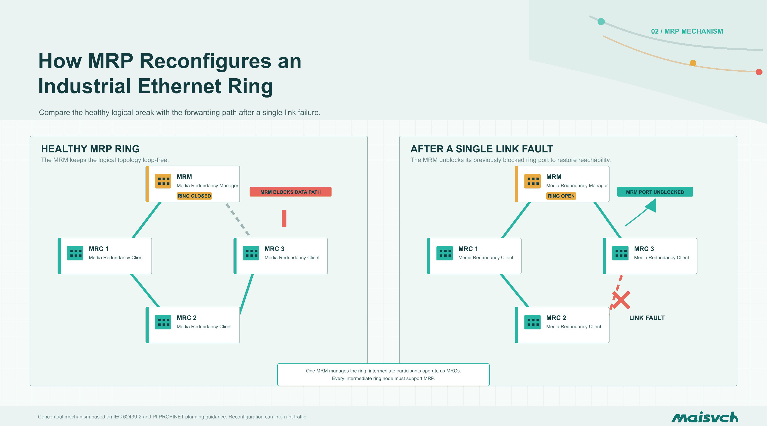
MRP is an industrial ring recovery protocol defined by IEC 62439-2:2021. The standard describes deterministic reaction to a specified single failure of an inter-switch link or switch under the control of a dedicated Media Redundancy Manager.
One node operates as the Media Redundancy Manager, or MRM. The other participating nodes operate as Media Redundancy Clients, or MRCs. The manager supervises the ring and keeps the normal topology loop-free. When a qualifying fault is detected, the ring changes state so traffic can reach nodes through the remaining path.
MRP is closely associated with PROFINET installations, but “PROFINET device” and “MRP-capable ring participant” are not interchangeable labels. The PROFINET redundancy planning guideline states that devices located in the MRP ring must support MRP according to IEC 62439-2.
An endpoint without MRP support can still connect as a spur to an MRP-capable switch. It should not be inserted as an intermediate ring node merely because it has two Ethernet ports.
The same PI guideline states that MRP reconfiguration must not exceed 200 ms. In its tunnel planning example, the ring is limited to 50 devices to comply with that target, and the guideline warns that the permitted number may be lower depending on the manufacturer. Faster MRP profiles should therefore be treated as device- and configuration-specific capabilities, not assumed from the acronym.
Where MRP fits well
MRP deserves priority when:
- the project specification explicitly requires IEC 62439-2;
- a PROFINET machine or production network uses devices designed to participate in an MRP ring;
- deterministic single-fault behavior is more important than topology flexibility;
- the selected manager, clients, profile, ring size, and firmware are documented as compatible;
- operations staff need a clear industrial ring state and diagnostic model.
What to verify before selecting MRP
Do not reduce MRP selection to one recovery-time figure. Verify:
- supported MRP role: manager, client, or automatic manager selection;
- supported recovery profile and the conditions attached to it;
- maximum validated ring size;
- whether every intermediate node participates correctly;
- support for MRP ring interconnection if separate rings must be connected redundantly;
- VLAN, multicast, PROFINET, and diagnostic behavior during failure and restoration;
- cross-vendor and cross-firmware test evidence.
The acronym also needs context in SEO copy and specifications. In this article, MRP means Media Redundancy Protocol, not Material Requirements Planning or Metro Ring Protocol.
How ERPS Protects an Ethernet Ring
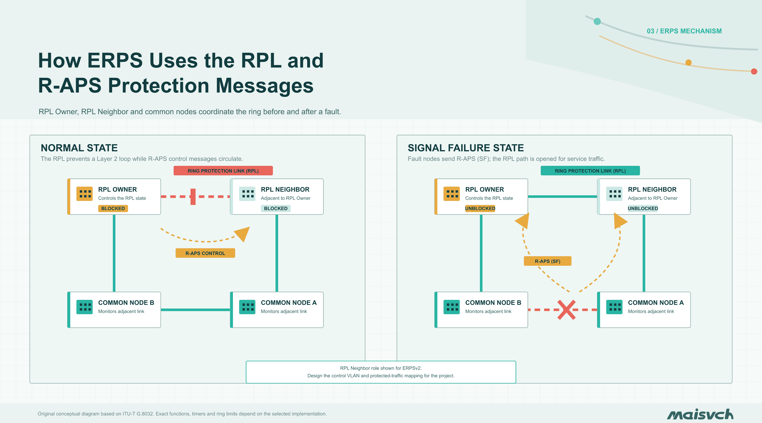
ERPS is defined by ITU-T G.8032/Y.1344. The in-force recommendation covers Ethernet ring protection switching, including protection conditions, revertive and non-revertive behavior, R-APS control messages, and ring-interconnection models.
An ERPS design identifies a Ring Protection Link, or RPL. The RPL Owner controls the protected link state, while other ring nodes monitor their adjacent links and exchange Ring Automatic Protection Switching messages. Under normal conditions, the protected path is blocked for the relevant traffic. When a qualifying signal failure occurs, the ring protection state changes and the alternate path becomes available.
ERPS grew from carrier Ethernet requirements, but its architecture also fits industrial networks built around geographically distributed fiber rings. Typical examples include railway stations, tunnels, road cabinets, photovoltaic fields, substations, wind farms, ports, and city surveillance networks.
Where ERPS fits well
ERPS is a strong candidate when:
- the network is intentionally designed as a managed Ethernet ring;
- the specification requires ITU-T G.8032 or ERPSv1/v2 support;
- the project includes long-distance fiber, many distributed cabinets, or ring interconnection;
- service VLANs or multiple protected instances need to be mapped deliberately;
- fast protection switching is required and the exact switch model has documented and testable performance.
What “supports ERPS” does not tell you
The feature name alone does not establish:
- whether the switch supports ERPSv1, ERPSv2, or both;
- single-ring versus interconnected-ring behavior;
- the number of ERP instances;
- RPL Owner and RPL Neighbour capabilities;
- control VLAN and service VLAN restrictions;
- revertive and non-revertive options;
- the validated ring size;
- actual recovery under the project’s traffic load and failure mode.
Two switches can both list ERPS while exposing different configuration limits. Compare the function table, user manual, firmware release notes, and conformance evidence before treating them as interchangeable.
MRP vs ERPS for PROFINET Networks
The presence of PROFINET traffic does not by itself decide between MRP and ERPS. The deciding question is whether the protected ring is part of the PROFINET redundancy design or an Ethernet transport domain carrying PROFINET traffic.
Choose MRP as the starting point when PROFINET devices participate directly in the ring, the engineering specification requires IEC 62439-2, and the MRM/MRC roles, ring ports, device count, and reconfiguration target are controlled within the automation project.
Consider ERPS for a separate managed backbone when G.8032 is the governing requirement and PROFINET traffic crosses that backbone as one service among others. In that design, verify end-to-end latency, jitter, multicast behavior, VLAN mapping, application relationships, and recovery at the PROFINET endpoints. ERPS support does not turn endpoints into MRP participants, and carrying PROFINET frames does not make an ERPS ring an MRP ring.
If the application requires nearly interruption-free PROFINET IRT communication, ordinary MRP may still be insufficient. The PI planning guideline describes MRPD as an extension based on MRP and PROFINET IRT, with additional endpoint and network requirements. Treat that as a different architecture and compatibility decision, not as a faster setting that can be enabled on any MRP ring.
A Practical Decision Framework
Step 1: Define the maximum permissible interruption
Write the requirement in application terms:
- maximum consecutive lost control cycles;
- maximum PLC-to-I/O interruption;
- maximum acceptable video gap;
- watchdog and safety-state behavior;
- whether any packet loss is acceptable;
- whether a second interruption during link restoration is acceptable.
“Fast recovery” is not a testable requirement. “The PLC-to-remote-I/O exchange shall not experience an interruption longer than X under the specified single-link fault” is testable.
Step 2: Confirm the topology
Use RSTP as the first candidate when the network is a general bridged topology with redundant uplinks, trees, or mixed paths.
Use MRP or ERPS as the first candidate when the protected domain is a deliberately managed ring. If several rings connect together, define whether the project uses MRP interconnection, ERPS ring interconnection, a routed boundary, or another controlled architecture.
Do not close a cable loop first and decide the protocol later. The protocol roles, ports, VLANs, and failure domains belong in the topology design.
Step 3: Follow the application ecosystem
An IEC 62439-2 or PROFINET-oriented requirement points toward MRP. A G.8032 fiber-ring requirement points toward ERPS. A heterogeneous plant distribution network may favor RSTP.
The ecosystem does not replace testing, but it narrows the realistic device set and reduces integration risk.
Step 4: Check every ring participant
One unsupported intermediate device can invalidate the design. Record:
- exact model and hardware revision;
- firmware version;
- supported protocol and version;
- supported role;
- ring port type and speed;
- supported SFP modules;
- maximum ring size and instance count;
- management and alarm capability.
Step 5: Decide whether reconfiguration-based redundancy is enough
RSTP, MRP, and ERPS all take time to react and change the forwarding topology. If the application requires zero switchover or duplicate-frame delivery over independent paths, evaluate PRP, HSR, or IEEE 802.1CB FRER.
The fastest ring protocol is still the wrong architecture when the process cannot tolerate even its tested interruption.
Which Protocol Fits Which Industrial Application?
| Application | Starting point | Why | Verify before approval |
|---|---|---|---|
| Mixed plant distribution network | RSTP | Flexible across bridged tree, star, and redundant-uplink designs | Root placement, topology diameter, convergence test, VLAN and multicast behavior |
| PROFINET machine or production ring | MRP | IEC industrial ring model and strong PROFINET ecosystem alignment | Every ring node, MRM/MRC roles, recovery profile, ring size, firmware |
| Railway, tunnel, utility, or smart-city fiber ring | ERPS | Purpose-built Ethernet ring protection and distributed fiber fit | ERPS version, RPL roles, instances, VLAN mapping, interconnection, measured switching |
| Small isolated machine star | No ring protocol may be required | A simple star can provide better fault isolation with less configuration | Central switch resilience, power, spare ports, maintenance requirement |
| Process requiring seamless failover | PRP, HSR, or FRER evaluation | Reconfiguration protocols can lose frames during switching | Endpoint support, duplicate network paths, supervision, bandwidth and test evidence |
These are starting points. A railway project can use RSTP at one layer and ERPS at another. A factory can use MRP inside a machine and RSTP in the plant distribution network. The important rule is that each Layer 2 failure domain has one documented control strategy.
Worked Design Example: A Hypothetical 24-Switch Fiber Ring
The following scenario is a design exercise, not a Maisvch customer case or laboratory benchmark. Consider a hypothetical water-treatment site with 24 outdoor cabinets connected by fiber. The ring carries PLC and remote-I/O traffic, camera streams, SNMP alarms, and engineering access. The control specification allows no more than 100 ms of application interruption after a single fiber cut.
The decision cannot be made from the protocol names alone:
- RSTP is widely supported, but a generic RSTP feature entry does not prove a 100 ms application outage across 24 switches. The design needs measured worst-case evidence for the exact topology.
- MRP remains a candidate only if every ring node supports a compatible recovery profile that fits the requirement and the project can assign the required manager and client roles.
- ERPS remains a candidate only if the selected model, ERPS version, ring size, optical links, and configuration have documented and tested switching behavior inside the target.
Separating cameras and control traffic with VLANs and QoS is good network design, but it does not shorten a physical link outage by itself. The redundancy protocol must recover the path, and the PLC communication must remain within its own timeout.
The test result, not the protocol label, closes the selection.
Can RSTP, MRP, and ERPS Coexist?
They can exist in the same plant, but they should not compete to control the same physical ring.
A practical architecture might use:
- MRP inside a PROFINET machine ring;
- RSTP across plant aggregation switches;
- ERPS on a distributed fiber backbone.
The boundaries must be explicit. Document which protocol controls each link, which VLANs cross the boundary, where the RSTP root resides, where MRP manager and client roles reside, and which ERPS node owns the RPL.
Do not enable several redundancy protocols on the same ports and expect the switches to negotiate the safest result. Interactions between blocked ports, topology-change messages, forwarding databases, and control VLANs must be designed and tested.
How to Test an Industrial Ethernet Redundancy Design
A factory acceptance test should measure the application path, not only switch status.
| Test | What to do | What to record | Example acceptance basis |
|---|---|---|---|
| Baseline | Run normal production traffic at expected and peak load | Latency, jitter, packet loss, CPU utilization, optical levels and alarms | All baseline values remain inside the project’s normal operating limits |
| Single-link failure | Disconnect each representative copper or fiber segment | Longest traffic interruption, lost frames, protocol events, affected devices | Every measured application interruption stays below the specified maximum |
| Switch power failure | Remove power from a non-manager node and from each critical control-role node | Recovery behavior, adjacent-link detection, application reconnect time | Surviving devices recover as designed; endpoints on the failed switch are reported separately |
| Remote or unidirectional fault | Simulate a failure that may not create a clean local link-down event | Detection method, alarm timing and recovery | The fault is detected, alarmed and recovered within the documented requirement |
| Link restoration | Restore the failed path | Revertive behavior, second interruption, MAC relearning and duplicate traffic | Restoration creates no unapproved second outage, loop or traffic duplication |
| High-load failure | Repeat faults with multicast, video and engineering traffic active | Worst-case application outage and control-traffic integrity | Results remain inside the requirement at the specified peak load |
| Repeated transition | Perform multiple fail-and-restore cycles | Stability, state consistency, log quality and manual intervention requirement | Every cycle returns to the intended state without manual recovery |
Use packet capture timestamps at both ends of the protected path. Record the exact switch model, firmware, configuration file, SFP, ring size, traffic profile, and fault location. A claim that cannot be reproduced is not commissioning evidence.
Selecting a Compatible Industrial Ethernet Switch
Protocol support is only one line in the switch specification. The protected network also depends on:
- the number, speed, and type of ring ports;
- copper, SFP, SFP+, and connector requirements;
- optical budget and supported transceivers;
- operating temperature and installation environment;
- redundant power inputs and independent power sources;
- alarm relay, SNMP traps, syslog, RMON, and port mirroring;
- VLAN, QoS, IGMP snooping, ACL, and management security;
- replacement-unit and configuration-backup procedures.
The Industrial Ethernet Switch Buyer’s Guide provides a broader specification framework, while the managed vs unmanaged industrial switch guide explains why a ring participant normally requires managed-switch functions.
Where Maisvch Switches Fit
Maisvch publishes RSTP and ERPS support for selected managed industrial Ethernet switches. Examples include:
- MISCOM8036GX-4XGF-24GF-8GT, whose public product page lists ERPSv1/v2 and STP/RSTP/MSTP;
- MISCOM7212G-4GF-8GT, whose published datasheet lists MW-Ring, ERPSv1/v2, and STP/RSTP;
- MISCOM6024-4F, whose product page lists ERPSv1/v2 and RSTP compatible with STP.
These examples do not establish portfolio-wide support or guarantee one recovery result for every ring. Confirm the exact model, firmware, protocol version, port configuration, ring scale, and recovery requirement for the project.
The cited public references do not establish MRP support for these examples. If IEC 62439-2 MRP is mandatory, request written confirmation for the exact model and firmware before including the switch in the bill of materials.
The broader Maisvch industrial Ethernet switch portfolio includes managed DIN-rail, rack-mount, fiber, PoE, Layer 2, Layer 3, and 10G options. Start with the redundancy requirement, then filter by ports, environment, power, management, and industry standard.
Evidence boundary: product-function statements in this section trace only to the cited public pages or documents. They are not portfolio-wide claims, require a final manual source check before publication, and do not replace project-specific written confirmation or a failure test.
Industrial Ethernet Redundancy Selection Checklist
Before approving a protocol and switch, confirm:
- Maximum permissible application interruption is documented.
- Physical and logical topologies are both drawn.
- The selected protocol controls one clearly defined failure domain.
- Every intermediate ring node supports the required protocol, version, role, and firmware.
- Ring size, port speed, fiber type, SFP, and optical budget are verified.
- VLAN, multicast, QoS, and control-protocol behavior are documented.
- Power failure is covered, not only cable failure.
- Restore and revertive behavior are tested.
- Mixed-vendor interoperability is demonstrated where required.
- Packet loss and application recovery are measured under realistic load.
- Configuration backups, alarms, logs, and replacement procedures are available.
- Vendor performance claims include conditions and reproducible test evidence.
Frequently Asked Questions
Which is faster: RSTP, MRP, or ERPS?
There is no defensible universal ranking without defining the switch implementation, topology, ring size, failure mode, traffic, and measurement method. MRP and ERPS are ring-specific mechanisms with more controlled recovery models than general-purpose RSTP, but the exact result must come from the selected device and project test.
Can RSTP be used in an industrial Ethernet ring?
Yes. RSTP can create a loop-free logical topology on a physically redundant ring. It is appropriate when its measured convergence meets the application requirement and the design does not need a ring-specific MRP or ERPS architecture.
Is MRP only for PROFINET?
No. MRP is standardized independently as IEC 62439-2. It is, however, strongly associated with PROFINET automation networks, and PROFINET planning guidance provides an established ecosystem for MRP-capable devices and engineering.
Should a PROFINET network use MRP or ERPS?
Use MRP as the starting point when the PROFINET devices themselves participate in the protected ring and IEC 62439-2 is part of the automation design. ERPS may suit a separate G.8032 backbone that transports PROFINET alongside other Ethernet services, but it does not replace MRP roles inside a PROFINET MRP ring. Verify the complete endpoint-to-endpoint recovery requirement in either case.
Is ERPS the same as RSTP?
No. RSTP builds a spanning tree across a bridged network. ERPS is a ring protection protocol based on G.8032 roles, RPL control, and R-APS messaging. Their configuration model and intended topology differ.
Can unmanaged switches participate in an MRP or ERPS ring?
An intermediate ring node normally needs to understand and participate in the selected redundancy protocol. An unmanaged switch may pass ordinary Ethernet frames, but inserting it into a managed ring can invalidate detection, control, diagnostics, and recovery assumptions.
Can different brands run in the same ring?
Standards-based support improves the possibility of interoperability, but it does not prove it. Verify protocol version, roles, timers or profiles, VLAN behavior, firmware, and ring limits, then run a mixed-vendor failure and restoration test.
Does a faster recovery protocol reduce normal network latency?
Not necessarily. Protection switching time describes behavior after a fault. Normal forwarding latency depends on switch architecture, processing mode, link speed, queueing, traffic load, QoS, and hop count.
What happens when a switch fails instead of a cable?
A switch failure can remove two adjacent links and the forwarding functions of that node. The protocol and ring design must support that failure type, and any endpoints connected directly to the failed switch will still be unreachable unless they have their own redundant attachment.
Can MRP and RSTP be used in the same plant?
Yes, in separate and documented redundancy domains. For example, MRP can protect a machine ring while RSTP controls redundant uplinks in the plant distribution layer. The boundary between the domains must not create an uncontrolled Layer 2 loop.
Is MRP the same as Metro Ring Protocol?
No. In industrial automation, MRP usually means Media Redundancy Protocol under IEC 62439-2. Some networking products have used the same acronym for Metro Ring Protocol, so specifications should always write the full protocol name and standard.
When should PRP, HSR, or FRER be considered?
Evaluate them when the application cannot tolerate the packet loss or switching interval inherent in a reconfiguration-based protocol. They use duplicated paths or replicated frames and require a different endpoint, bandwidth, supervision, and commissioning model.
What is Ethernet Ring Protection Switching?
Ethernet Ring Protection Switching, or ERPS, is an Ethernet ring redundancy protocol defined by ITU‑T G.8032. It prevents Layer 2 loops by blocking a designated Ring Protection Link during normal operation and restoring an alternate forwarding path after a qualifying fault. Actual recovery performance depends on the switch model, firmware, ring size, configuration and test conditions.
What is an ERPS switch?
An ERPS switch is a managed Ethernet switch that implements the required ITU‑T G.8032 control functions, including RPL roles and R-APS messaging. Products may differ in supported ERPS versions, ring instances, interconnected-ring functions, VLAN behavior and recovery performance, so protocol support must be confirmed for the exact model and firmware.
Final Recommendation
RSTP, MRP, and ERPS solve related problems, but they are not interchangeable speed tiers.
Start with RSTP when the network needs flexible, broadly supported bridge redundancy and can accept tested, topology-dependent reconvergence. Start with MRP when an IEC 62439-2 industrial or PROFINET-oriented ring is the governing requirement. Start with ERPS when a managed Ethernet fiber ring or interconnected-ring architecture calls for G.8032 behavior.
Then challenge the selection with real faults. Break the link, remove power, restore the path, load the network, and measure the application. The correct industrial Ethernet redundancy protocol is the one that the complete system can demonstrate under the conditions it will face in service.
To evaluate a Maisvch switch for a redundancy project, prepare the topology, node count, fiber and copper interfaces, SFP requirements, protocol standard and version, maximum permissible interruption, traffic mix, ambient conditions, and power architecture. That information allows a model and firmware to be checked against the network requirement instead of selected from a protocol checkbox.
Share that project information with Maisvch to confirm the appropriate model, firmware, supported redundancy functions, and evidence required for acceptance. The confirmation should be tied to the exact bill of materials rather than inferred from another model in the same product family.
Source Review and Revision Notes
- Standards references reviewed: IEEE 802.1Q-2022, IEC 62439-2:2021, ITU-T G.8032, and the 2023 PI PROFINET redundancy planning guideline.
- Maisvch product-function statements are limited to the specific cited public references; each source must be checked manually before publication, and no portfolio-wide MRP claim has been made.
- The 24-switch water-treatment scenario is hypothetical and is not presented as measured project data.