Your PLC records a fault, a camera captures a part, and a sensor reports a change. All three devices display the same second. But can you tell whether their events happened together—or which happened first? When each device uses its own clock, the timestamps may disagree even though the Ethernet connection works perfectly.
Precision Time Protocol (PTP) is the clock-synchronization protocol defined by IEEE 1588. It uses timestamped messages to estimate network delay and the difference between device clocks, then disciplines those clocks toward a common reference. A suitable implementation can achieve sub-microsecond alignment; your actual accuracy depends on the complete timing path. The IEEE 1588 standard defines that protocol framework.
For your industrial project, the useful question is what that common clock lets your devices do—and what equipment must support it.

What problem does Precision Time Protocol solve?
You can set two clocks to the same time and still see them gradually separate. Their oscillators do not run at exactly the same rate. A timestamp attached to a measurement can therefore contain both the real event time and the error of the device's local clock.
Network delay creates a second problem. If a device receives a message saying “the time was 10:00:00,” some time has already passed while that message travelled. Simply copying the transmitted time would leave the receiving clock late.
PTP addresses both problems through repeated timing exchanges. Your devices estimate the clock difference, account for measured delay and continue adjusting as their clocks drift. You can then compare measurements or schedule supported actions against the same time base.
Keep two requirements separate when you specify the project:
- Relative alignment: how closely your devices must agree with one another.
- Absolute time: how closely their timestamps must match UTC or another external reference.
A network can have closely aligned devices while its common clock has the wrong date or time of day. The quality and traceability of the time source matter when you need absolute timestamps.
What devices do you need in a PTP network?
Start with three places in the timing path: the device supplying time, the network carrying it and the devices using it. “Grandmaster,” “boundary clock” and “transparent clock” describe timing roles, rather than connector types or enclosure styles.
| Role | What it does | What you should identify in your installation |
|---|---|---|
| Grandmaster clock (GM) | Supplies the reference time for a PTP domain. | Which device is intended to provide time, its reference source, and any backup candidate. A supported endpoint or clock appliance may fill this role. |
| Boundary clock (BC) | Synchronizes upstream and distributes time through downstream PTP ports. | Whether a switch supports the required BC implementation and profile, and how its ports are configured. |
| Transparent clock (TC) | Measures relevant message residence time and updates correction information as messages pass through. | Whether the switch supports the TC type and delay mechanism your profile requires. |
| Ordinary clock (OC) | Has one PTP port; it may provide or receive time. | Which endpoint clock is being synchronized and whether your application actually uses that clock. |
These roles are described in the IETF Enterprise PTP Profile. A boundary clock creates a new downstream timing exchange; a transparent clock contributes correction information to an exchange passing through it. Either approach still requires a compatible design and verification.
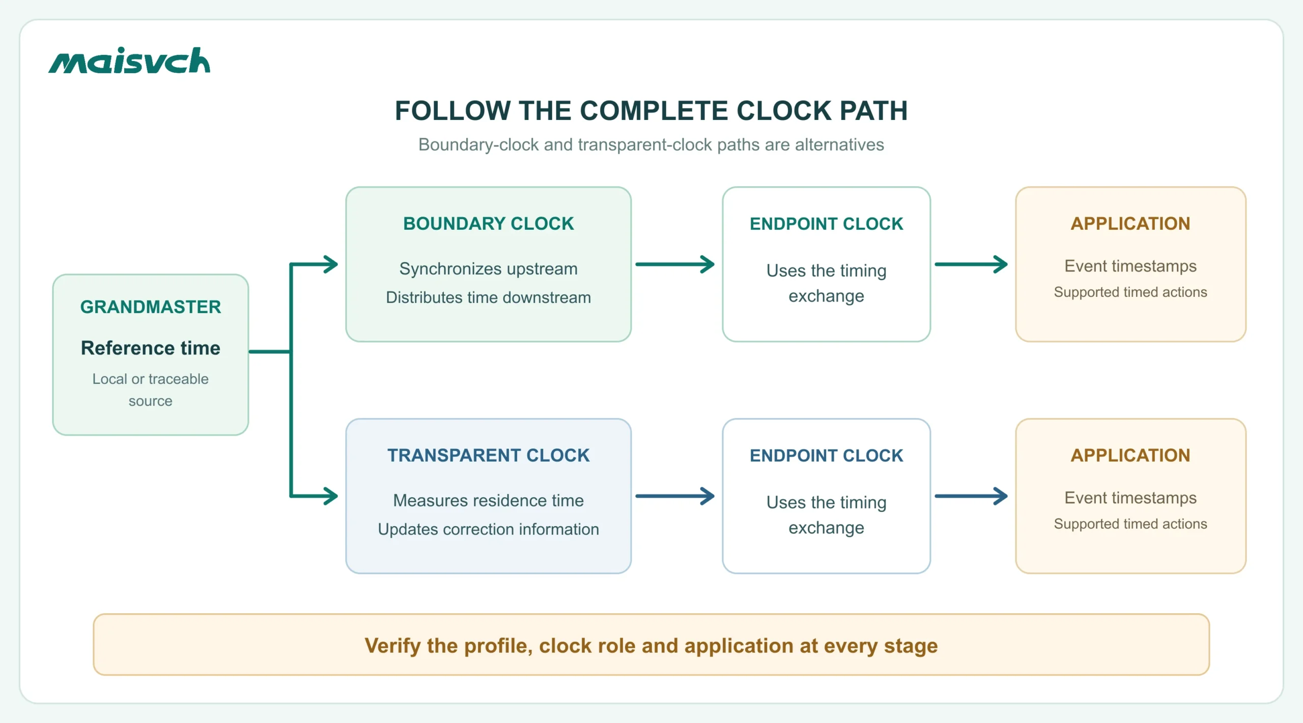
An ordinary Ethernet switch may forward PTP traffic without performing either clock function. Whether that is acceptable depends on your profile, traffic, topology and timing-error budget. Record each switch in the actual path; a “PTP” feature on one device does not describe the whole network.
How does Precision Time Protocol work?
The protocol first establishes which clock provides time. In a typical domain, candidate clocks advertise information in Announce messages, and the applicable best-clock selection algorithm chooses the time source. The selection rules depend on the profile and configuration; they are not a substitute for checking the actual time source.
The receiving clock then needs to answer two questions: How far ahead or behind am I? How long did the timing messages take to travel? The following is a simplified two-step, end-to-end (E2E) exchange.
1. Capture the forward-path timestamps
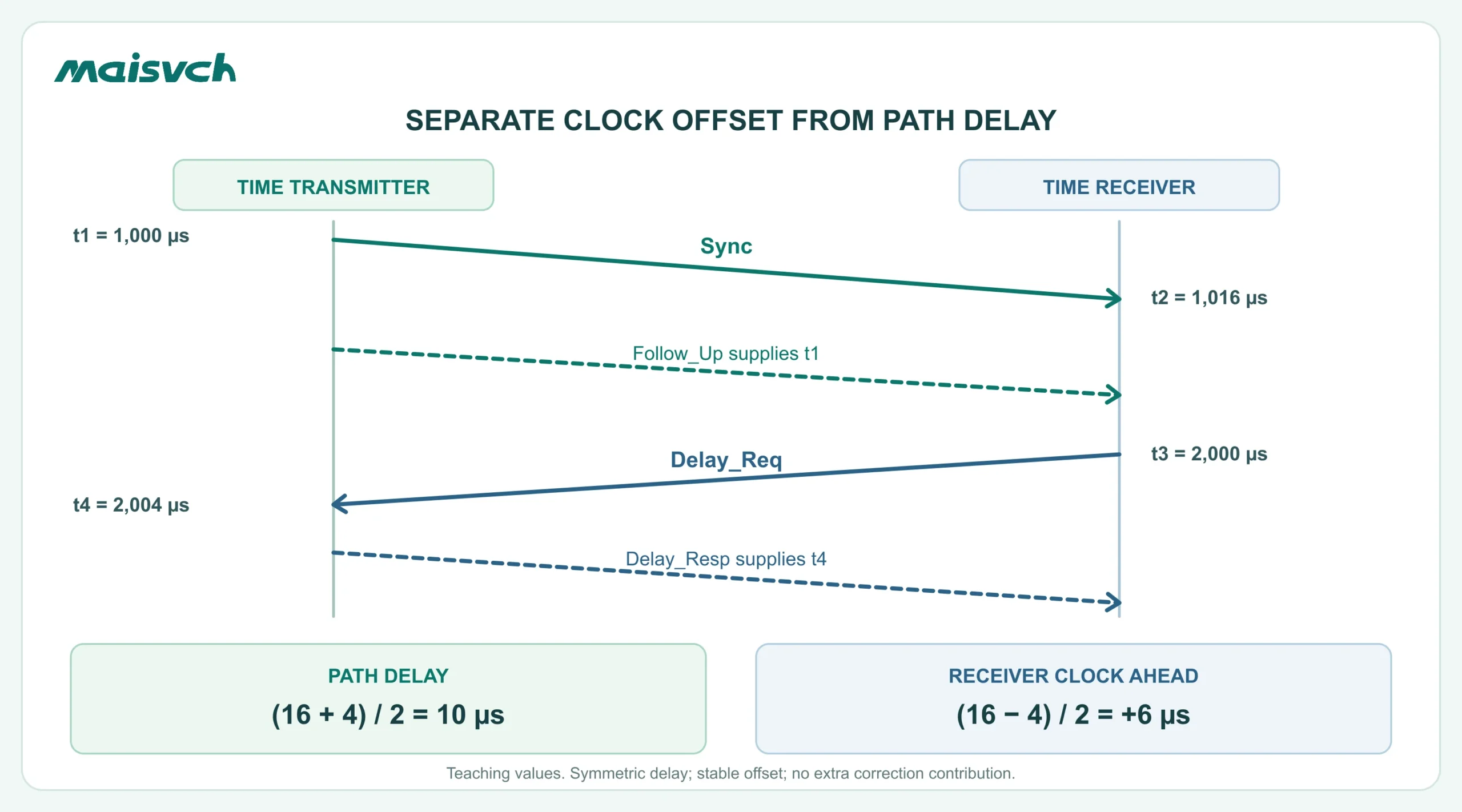
The time-transmitting clock sends a Sync message and records its departure time, t1. The receiving device records arrival time, t2, using its own clock. In two-step operation, a later Follow_Up supplies the precise t1 associated with that Sync.
The difference t2 − t1 includes both the network travel time and the difference between the two clocks. It cannot tell you either quantity by itself.
2. Measure in the reverse direction
The receiving device sends Delay_Req and records departure time t3. The time-transmitting clock records arrival time t4, then returns t4 in Delay_Resp. Now the receiver has timing information from both directions.
3. Estimate delay and clock offset
For an ideal exchange with equal forward and reverse delay:
mean path delay = [(t2 − t1) + (t4 − t3)] / 2
clock offset = [(t2 − t1) − (t4 − t3)] / 2
Here, a positive offset means the receiving clock is ahead of the transmitting clock. NIST's IEEE 1588 application paper describes the Delay Request-Response calculation.
A four-timestamp example you can check
Suppose the timestamps below use the same arbitrary time origin. These are teaching values, not a device performance result.
| Timestamp | Recorded event | Clock used | Value |
|---|---|---|---|
| t1 | Sync leaves the transmitter | Transmitter | 1,000 µs |
| t2 | Sync reaches the receiver | Receiver | 1,016 µs |
| t3 | Delay_Req leaves the receiver | Receiver | 2,000 µs |
| t4 | Delay_Req reaches the transmitter | Transmitter | 2,004 µs |
The forward difference is 16 µs; the reverse difference is 4 µs. Their average is a 10 µs path delay. Half their difference is a 6 µs clock offset: the receiving clock is ahead by 6 µs.
This example assumes equal forward and reverse delay, a stable offset during the exchange and no additional correction-field contribution. A real implementation must account for the relevant corrections and use a clock-control loop to maintain alignment. Clock adjustments may be gradual; you should not assume every update instantly steps the application clock.
Other profiles can use peer-to-peer (P2P) link-delay measurement. In one-step operation, the required timing information is incorporated during transmission rather than provided through the same Follow_Up pattern. Those choices concern implementation and compatibility; one-step is not automatically a guarantee of better accuracy. Your selected devices and profile determine the supported behavior.
What determines PTP synchronization accuracy?
PTP provides a way to synchronize clocks. The name alone does not specify the error your installation will achieve. Before you accept a precision figure, check what was measured, against which reference, and under what conditions.
Timestamp location matters. A software timestamp can include variable operating-system, driver and processing delay. Hardware timestamping captures the event closer to the Ethernet interface, reducing that uncertainty. However, timestamp resolution and actual synchronization error are different quantities. Texas Instruments' synchronization application report illustrates both timestamp placement and the limits of software-reported measurements; its results apply to its stated test setup.
Path symmetry matters. The simple calculation above assumes equal delay in both directions. A different route or unequal transmit/receive delay can bias the result. For example, if forward delay exceeds reverse delay by 4 µs, the ideal estimator's offset is biased by 2 µs. That is a consequence of the equation, not a correction that every device automatically applies.
The complete clock path matters. Include the reference source, grandmaster, intermediate devices, endpoint clock and application. Test with the expected traffic and topology. A stable offset reported by one endpoint does not, by itself, prove the accuracy of a camera exposure or PLC output.
For your first evaluation, ask for the test's reference, measurement method, device and firmware versions, switch path, traffic conditions and observation period. That information makes a precision number useful.
Where is PTP useful in industrial Ethernet?
PTP becomes useful when your application needs measurements or actions to share a sufficiently accurate time base.
- Distributed measurements and event records: you can align data from supported sensors, controllers or IEDs instead of interpreting unrelated local timestamps. The application determines the necessary error limit.
- Machine vision: synchronized camera clocks help relate images to a common time. Scheduled acquisition still requires the camera's supported features and configuration. Basler's camera PTP documentation treats clock synchronization and time-based acquisition as related deployment tasks.
- Coordinated equipment: a shared clock can support time-based control or data acquisition when the endpoints are designed to act on it. Verify the complete application's timing behavior, including its communication and processing delays.
Think of the chain as synchronize the clock → timestamp an event or schedule an action → verify the application result. Buying a timing-capable switch addresses only part of that chain.
How do PTP, NTP and gPTP relate?
PTP and NTP both support clock synchronization, with different implementation and deployment choices. If you are deciding which approach fits your project, use the separate PTP vs NTP comparison. This introductory article focuses on how a PTP path works.
gPTP is the timing approach defined by IEEE 802.1AS, using IEEE 1588 specifications where applicable. Generic PTP support does not establish compatibility with a particular 802.1AS implementation. Check the required revision, role and configuration.
TSN includes a wider collection of IEEE 802.1 mechanisms for time-sensitive networks. A common time base can support scheduled traffic, but synchronizing clocks alone does not guarantee a packet deadline. See TSN vs PTP and the IEEE TSN Task Group for that broader context.
Questions to resolve before your first PTP deployment
Does PTP need GPS or GNSS?
No. Devices can synchronize to a local grandmaster without a satellite reference. If your timestamps must be traceable to UTC, you need a suitable reference and a documented traceability path. If you only need devices to agree with one another, the requirement is different. Source loss and long-term drift still deserve attention.
Does every device on the Ethernet network need PTP?
Devices whose clocks or timed actions must participate need suitable support. Other Ethernet devices may share the network, subject to the design's traffic and profile requirements. Intermediate switches need to be evaluated along the timing path; ordinary packet forwarding and PTP-aware timing functions are different capabilities.
Will two devices that both support PTPv2 communicate correctly?
Check their profiles and settings before assuming so. IEEE 1588-2008 is commonly called PTPv2; later implementations may add capabilities under IEEE 1588-2019. Version labels do not resolve transport, domain, delay mechanism, clock-role or timestamping requirements. The LinuxPTP configuration documentation demonstrates those separate choices.
Does PTP synchronize my operating system and application automatically?
Verify which clock is disciplined. On some systems, the network interface has a PTP hardware clock while the operating system uses another clock. Your software must read the appropriate clock or have a supported synchronization path between them. The Linux PTP hardware-clock documentation explains that distinction for Linux implementations.
Check your PTP network requirements
Before choosing hardware, fill in the following short inventory. Unknown answers are useful: they identify which device manuals or supplier confirmations you need next.
| Question | Information to collect |
|---|---|
| What must share time? | Endpoint models, the measurements or actions involved, and whether the application uses synchronized time. |
| How close must the clocks agree? | Required error limit, relative alignment versus UTC, and the application's acceptance method. |
| Who provides the reference? | Intended grandmaster, reference input, backup source and behavior after reference loss. |
| What is the complete timing path? | Every switch, link, copper/fiber section and relevant traffic source between the reference and endpoints. |
| Can the timing implementations interoperate? | IEEE version/revision, profile, domain, transport, E2E/P2P, clock roles and supported one-/two-step behavior. |
| How will you validate it? | Expected source identity, synchronization state, measured error under load, and recovery after a restart or source failure. |
Maisvch's PTP Ethernet switches provide a product route once you have those requirements. The public information for MISCOM8216PTP-4XGF-4GF-8GT lists IEEE 1588v2 (PTP) and IEEE 802.1AS (gPTP) support, with four 10G SFP+ ports, four Gigabit SFP ports and eight Gigabit RJ45 ports. Confirm the required clock role, profile, timestamping behavior and measured accuracy for your configuration with Maisvch before specifying the model.
To discuss your first PTP network, share the endpoint list, topology, desired timing error and any required profile with the industrial Ethernet switch manufacturer. Those details give the review a concrete starting point and help you identify the equipment and evidence your project needs.