If your PTP devices already synchronize through your existing Ethernet switch, do you need to replace it? A successful connection gives you part of the answer. You still need to know how closely the clocks agree when your production traffic increases or a link fails.
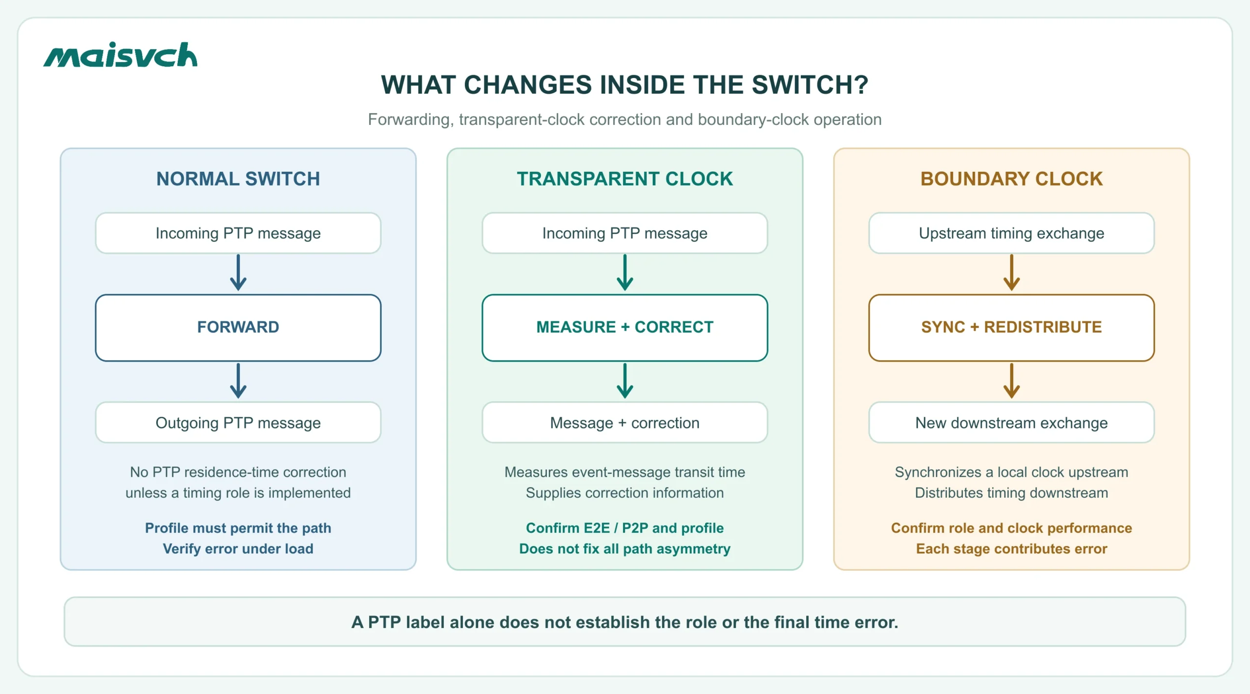
A normal Ethernet switch can forward PTP messages. A PTP-aware switch can add an explicit timing function, such as transparent-clock correction or boundary-clock operation. You need that function when your profile requires it or your existing timing path cannot meet the project's time-error limit under the conditions you must support.
In this comparison, normal switch means PTP-unaware, not “commercial instead of industrial.” Some general-purpose managed switches have PTP clock functions; some rugged industrial switches do not. Check the exact model, ports and firmware rather than judging the enclosure.
PTP switch vs normal switch: compare timing functions, not labels
Your purchasing decision becomes clearer when you separate packet forwarding from clock behavior.
| Description in a specification | What it means for your timing path | What you still need to confirm |
|---|---|---|
| Normal Ethernet switching | Forwards permitted Ethernet traffic. PTP may pass through without the switch participating in synchronization. | Required messages reach the endpoints; uncorrected path variation stays within your limit. |
| PTP passthrough | Indicates forwarding compatibility or a policy that permits PTP traffic. | The term alone does not establish a clock role, timestamping capability or accuracy. |
| QoS / traffic priority | Can reduce competition for an output queue. | Classification, scheduling and actual behavior under load; priority is not residence-time correction. |
| Transparent clock (TC) | Measures relevant PTP event-message transit time through the device and supplies correction information. | Required E2E/P2P behavior, profile, transport, supported ports and firmware. |
| Boundary clock (BC) | Synchronizes its local clock upstream and establishes downstream timing exchanges. | Profile, clock performance, port roles, topology and recovery behavior. |
TC and BC are different ways for a device to participate in the timing path. A switch may implement one, both or neither; support is configuration-specific. The LinuxPTP clock-role documentation describes the distinction. Neither role guarantees your final application accuracy on its own.
Can PTP work over an unmanaged Ethernet switch?
Yes, in a compatible design. For example, the IETF Enterprise PTP Profile permits paths containing TC, BC or neither. Its end-to-end delay exchanges can traverse PTP-unaware devices. That permission belongs to this profile; it does not make every PTP or gPTP design compatible with ordinary switching.
To retain an unmanaged switch, you need all of the following:
- Your required profile permits that type of path.
- The switch forwards the required traffic without blocking or filtering it.
- Your grandmaster and endpoints use compatible settings and suitable timestamping.
- The application reads or acts on the synchronized clock.
- The complete path meets your acceptance limit under expected traffic and failure conditions.
An unmanaged switch also gives you fewer options for inspecting or controlling traffic. If you cannot establish why timing fails under load, a managed switch may help you diagnose the network. It still needs explicit TC or BC support if that is the function you require.
For a profile that depends on adjacent peer-delay exchanges or time-aware participation along the path, check every relevant hop. Do not assume a working E2E trial proves that a P2P or IEEE 802.1AS configuration will work unchanged.
Why QoS is not a replacement for a PTP-aware switch
Imagine a camera frame has just started leaving the switch's output port. A PTP event message arrives immediately afterward. On a non-preemptive link, even a high-priority PTP frame may have to wait for that transmission to finish.
A 1,500-byte payload alone takes:
| Port rate | Payload serialization calculation | Time |
|---|---|---|
| 1 Gb/s | 1,500 × 8 ÷ 1,000,000,000 | 12 µs |
| 100 Mb/s | 1,500 × 8 ÷ 100,000,000 | 120 µs |
Actual link occupancy is longer because the Ethernet header, FCS, preamble and interpacket gap also consume wire time. These calculations show a possible blocking timescale, not a prediction of clock offset, an accuracy result or a Maisvch product test. Filtering, message direction, corrections and the rest of the path affect the synchronization result.
QoS can reduce contention; it does not measure how long a timing message spent inside the switch. A TC addresses that residence-time contribution through correction information. NIST's switch-cascading analysis explains why output queues and non-preemptive transmission matter even when timing traffic receives priority.
A TC also does not automatically remove propagation asymmetry between your links. A BC adds its own clock-control and timestamping performance to the path. If the forward and reverse paths differ, or a replacement link changes delay characteristics, include that condition in your evaluation.
Set a time-error budget before choosing a PTP switch
Start with a measurable requirement: which clock or event must be within what maximum error of which reference? “High precision” is not an acceptance criterion. Clock alignment, image exposure, PLC output timing and packet latency are different quantities.
For planning, you can allocate conservative maximum error contributions:
remaining switch-path budget = required error limit − other allocated contributions − reserve
The contributions must refer to time error at the same acceptance point. Do not add raw packet latency, a timestamp-resolution figure and an endpoint's diagnostic offset as though they were equivalent errors.
A budget example, not a synchronization benchmark
Suppose your requirement is for an endpoint clock to remain within 2.00 µs of a UTC-traceable reference. You propose the following allocations:
| Budget item | Illustrative allocation |
|---|---|
| Reference / grandmaster contribution | 0.30 µs |
| Endpoint timestamping and clock-control contribution | 0.40 µs |
| Residual link / asymmetry contribution | 0.30 µs |
| Engineering and measurement reserve | 0.20 µs |
| Remaining allowance for the switch path | 0.80 µs |
Here, 2.00 − 0.30 − 0.40 − 0.30 − 0.20 = 0.80 µs. If you provisionally share that allowance across two switch stages, each receives 0.40 µs. That is a design allocation to investigate, not evidence that either stage meets it. You still need suitable specifications and an end-to-end measurement.
These numbers are hypothetical. In your own worksheet, keep unsupported entries unknown, not zero. If your requirement is relative alignment between two endpoints, use a pairwise budget; a common reference error may cancel, so the UTC example should not be copied unchanged.
| Your project input | Value / evidence to record |
|---|---|
| Acceptance point and reference | Clock, timestamp or action; GM-relative, pairwise or UTC requirement |
| Required maximum time error | Limit, units, normal and failure conditions |
| Reference, endpoint and residual link contributions | Verified bounds or conservative allocations, with their sources |
| Reserve | Engineering margin and an appropriate measurement allowance |
| Remaining switch-path budget | Calculated allowance, compared with supported device behavior |
| Unknowns | Missing bounds, unsupported modes or unmeasured paths that prevent a decision |
This worksheet helps you ask the right supplier questions. It cannot certify a network by adding attractive datasheet numbers. Do not assume independent errors or use root-sum-square arithmetic unless your model justifies it.
Keep, upgrade one segment, or redesign the timing path?
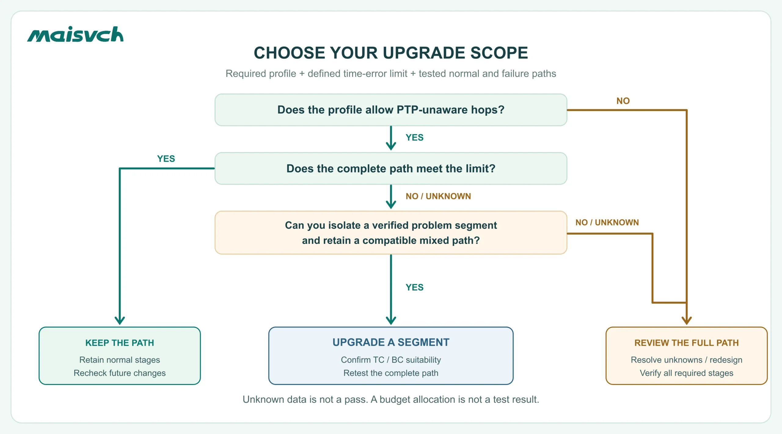
Use the budget together with the required profile. A budget cannot override a profile's interoperability requirements.
Keep your normal switches when the complete path passes
You can retain PTP-unaware switching where the profile allows it, forwarding is correct and the actual path meets your time-error limit. Test the busy period and any required backup route, not just an idle bench.
Reject this option if you only have a “synchronized” indicator, the profile requires unsupported participation, or unknown path behavior consumes the remaining margin. There is no universal “one switch is safe” or “below a certain hop count is safe” rule.
Upgrade the segment you can identify and verify
If a shared uplink or aggregation stage is the demonstrated problem, a targeted upgrade may be enough. A compatible TC can account for its own transit-time contribution; a suitable BC can establish a downstream timing stage.
The remaining PTP-unaware stages still need to fit the profile and error budget. Replacing one switch does not correct every unmeasured hop. Test the mixed path again, including the route used after a fault.
Redesign the timing path when requirements apply to every hop
If your profile requires time-aware participation throughout the relevant path, or several uncertain stages prevent you from meeting the limit, assess the whole timing chain. Include the reference, endpoints, switch ports, links and fallback behavior.
You may need multiple compatible PTP-aware stages rather than one new switch. That choice still requires verification; multiplying BCs or TCs does not make the final error zero.
If your project also needs bounded packet delivery, that is a separate communication requirement. Use the TSN vs PTP guide for that broader architecture decision.
Test a normal switch against a PTP-aware switch under load
Keep the grandmaster, endpoints, profile and traffic pattern consistent when you compare candidates. Record any differences you cannot hold constant, such as a new link speed, firmware or topology. Otherwise, you may attribute an improvement to the switch when another condition changed.

Use three operating conditions
| Condition | What you exercise | What you record |
|---|---|---|
| Idle baseline | Intended path with minimal competing traffic | Reference identity, settings, synchronization state, diagnostic offset and independently measured time error |
| Representative competition | Production traffic bursts, frame sizes and directions at expected peak load | Maximum measured error, variation, packet loss, alarms and whether the required limit is maintained |
| Required failure / recovery | A controlled link or reference change in a safe test environment | New path / source, time-error excursion, loss-of-sync interval and time to return within the limit |
Also record the observation period, sample rate, warm-up period, equipment and firmware, port speeds, E2E/P2P mode, one-/two-step behavior and traffic-generation method. Evaluate every required failover path; a redundant data connection is not automatically a compliant timing path.
Separate diagnostic offset from acceptance evidence
An endpoint's reported offset is useful for troubleshooting. It is an estimate produced by that implementation, not an independent measurement of the true error. For acceptance, use a suitable reference and measurement method—for example, supported time outputs measured with appropriately capable equipment—and account for measurement uncertainty.
If you are accepting an application event, measure that event. A well-aligned hardware clock does not prove a camera's exposure or a PLC output occurred at the requested time. NIST's timing-calibration study illustrates why measurement method and the complete clock path matter.
Agree on the failure criterion before the trial: maximum time error, allowable excursions, recovery time and how measurement uncertainty affects pass/fail. Average offset alone can hide the transient that disrupts your application.
What to confirm before specifying an industrial PTP switch
Send your supplier the profile, GM and endpoint models, topology, port speeds, traffic conditions and acceptance limit. Ask for confirmation against the exact hardware and firmware you will evaluate.
| Confirmation | Why it affects your upgrade |
|---|---|
| TC / BC role and applicable ports | A generic IEEE 1588 statement does not establish the timing function of every port. |
| Profile, revision, transport and domain | Matching “PTPv2” labels are not a complete interoperability check. |
| E2E/P2P and one-/two-step support | The entire relevant timing path must support the selected behavior. |
| Timestamping and performance evidence | Resolution is not synchronization accuracy; request measurement conditions and acceptance data. |
| VLAN, routing, aggregation or tunnel constraints | The intended forwarding path must match supported operation. |
| Source-loss and recovery behavior | Your backup arrangement must satisfy the agreed failure requirements. |
Maisvch's PTP Ethernet switches give you a product route for that review. For example, the published information for MISCOM8216PTP-4XGF-4GF-8GT lists IEEE 1588v2 (PTP), IEEE 802.1AS (gPTP), four 10G SFP+ ports, four Gigabit SFP ports and eight Gigabit RJ45 ports.
Those statements are a starting point. Confirm the required clock role, profile, ports and measured performance with Maisvch before matching the model to your upgrade. The port configuration or PTP label alone does not establish BC/TC capability or a specific time-error figure.
Questions that affect your upgrade
Is a managed switch automatically a PTP-aware switch?
No. Management, VLANs and QoS are separate capabilities. Look for the applicable clock role and supported PTP configuration in the exact model's documentation.
Must you replace every Ethernet switch with a PTP switch?
Not necessarily. Retain ordinary stages only where the required profile permits them and the complete path passes. If the profile requires participation at every relevant hop, or uncorrected stages exceed your budget, a partial upgrade is insufficient.
Does a PTP switch replace your grandmaster clock?
Only if the device explicitly supports the required time-source role and reference arrangement. TC support does not make a switch a grandmaster. BC operation also does not, by itself, establish a UTC-traceable reference source.
To evaluate your switch upgrade, share the completed budget, topology and test requirements with the industrial Ethernet switch manufacturer. You can then review a specific upgrade scope and sample configuration, with the unresolved timing capabilities identified before you order.