Your SCADA workstation can ping the new box. Its Ethernet link is up, and the RS485 LEDs flash. Yet every meter still times out. This is a common commissioning trap: the interfaces match, but the conversation does not.
A serial device server is sufficient when your host already sends and receives the original serial protocol through a Virtual COM port or transparent TCP/UDP connection. A Modbus gateway is required when a native Modbus TCP client must reach Modbus RTU or ASCII devices, or when the project needs Modbus-aware routing, transaction handling or supported polling functions. The model name alone is not decisive; verify the configured operating mode and the frames on both sides.
| Your host actually opens or sends | What must cross Ethernet | Best starting point |
|---|---|---|
| A Windows/Linux COM port from existing serial software | Original RTU/ASCII or proprietary serial bytes | Serial device server with a verified Virtual COM mode |
| A raw TCP or UDP socket and the application builds the serial frames | Original serial bytes encapsulated over IP | Transparent serial device server |
| Native Modbus TCP on port 502 | MBAP-framed Modbus TCP requests that must become RTU/ASCII frames | Modbus gateway |
| Several Modbus TCP clients sharing one RTU bus | Ordered transactions, address routing and controlled access | Modbus gateway with documented arbitration behavior |
| The gateway must poll registers and expose recent values | Model-specific pre-reading/cache and data-quality behavior | Modbus gateway with verified polling and freshness controls |

Modbus Gateway vs Serial Device Server Starts With the Host Frame
Do not begin with the connector count. Begin with one captured request from the PLC, SCADA, BMS or industrial PC.
A transparent serial device server carries the application bytes
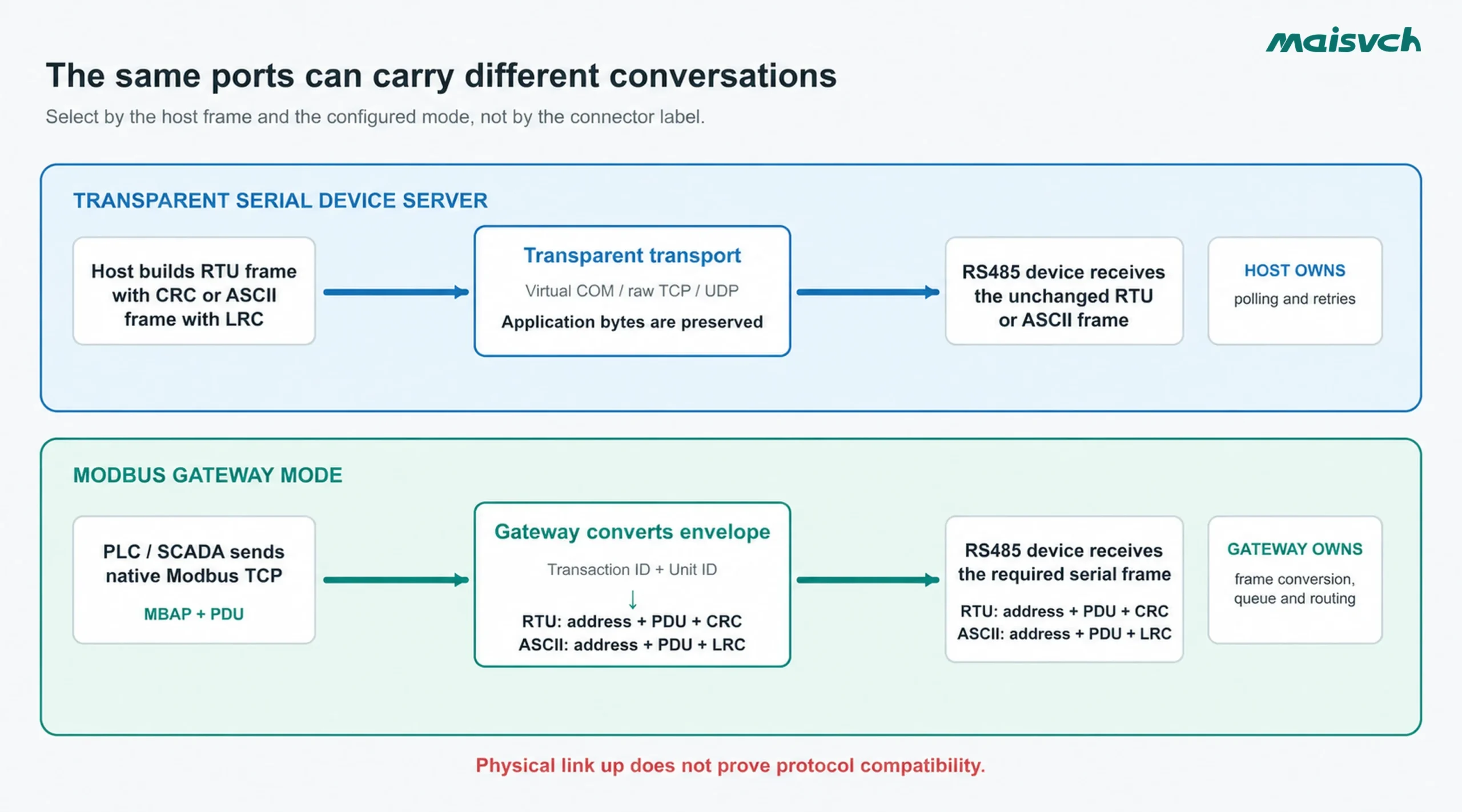
In a transparent path, the host still owns the serial conversation. It may use a Virtual COM driver, open a TCP socket, or send Modbus RTU-over-TCP. The device server packetizes the byte stream for Ethernet and recreates the byte stream at the serial port. It should not silently turn a Modbus TCP Application Data Unit into an RTU frame.
That makes transparent transport useful when:
- Your legacy software must continue opening
COM5or another local serial port. - Your application already creates the slave address, function code, data and RTU CRC.
- Your equipment uses a proprietary serial protocol rather than Modbus.
- You need a serial tunnel between two IP-connected locations.
TCP preserves byte order, but it does not preserve the original serial-message boundaries. Packetization time, maximum packet length, serial frame gaps and application timeouts still need a bench test. If your current question is port count, interface or isolation rather than protocol behavior, use the separate guide on how to choose a serial device server.
A Modbus gateway rebuilds the transport envelope
A native Modbus TCP request has a seven-byte MBAP header. It includes a Transaction Identifier, Protocol Identifier, Length and Unit Identifier. A Modbus RTU frame instead uses the serial server address and a CRC. A gateway removes or adds the appropriate envelope while preserving the Modbus function and data.
Der Modbus TCP/IP Messaging Implementation Guide states that the Unit Identifier is used for routing through a bridge or gateway to a server on a serial subnetwork. It also explains the crucial behavioral mismatch: a serial client normally waits for one response before sending the next request, while Modbus TCP can have several requests in progress. The gateway must make those behaviors compatible.
If your SCADA sends native Modbus TCP directly through a transparent server, the RTU meter does not receive a valid RTU frame with the required CRC. Link LEDs may flash, but no valid reply is produced. For a deeper protocol comparison, see Modbus RTU vs Modbus TCP.
Who Owns the Modbus Poll Cycle?
This question often resolves the selection faster than the product title.
When the host owns polling
Your PLC, SCADA driver or custom application chooses the device address, function code, register range, retry count and scan interval. It decides when a request has timed out and whether to try again. If it already speaks RTU/ASCII through a COM port or transparent socket, a serial device server can be enough.
You still need to verify packetization and exclusivity. A datasheet statement such as “supports eight TCP clients” describes network connections; it does not prove that eight independent applications may safely issue writes to one half-duplex RS485 line. Define one polling owner or document an arbitration mechanism.
When the gateway owns part of polling
Some Modbus gateways can actively pre-read a configured register list and make recent values available to network clients. That can reduce repeated traffic on a slow serial bus, but it changes the system contract. You must define:
- Which function codes and register ranges the gateway polls.
- The poll interval, retry count and timeout per device.
- Whether reads come from cache or trigger an immediate serial request.
- How old a value may be before it becomes stale.
- How stale, failed or never-read data is identified to the client.
- Whether client writes bypass, update or invalidate cached values.
Do not assume every product marketed as a Modbus gateway includes pre-reading. Do not assume enabled pre-reading is safe without a data-age rule.
Multiple TCP Clients Still Share One Serial Conversation
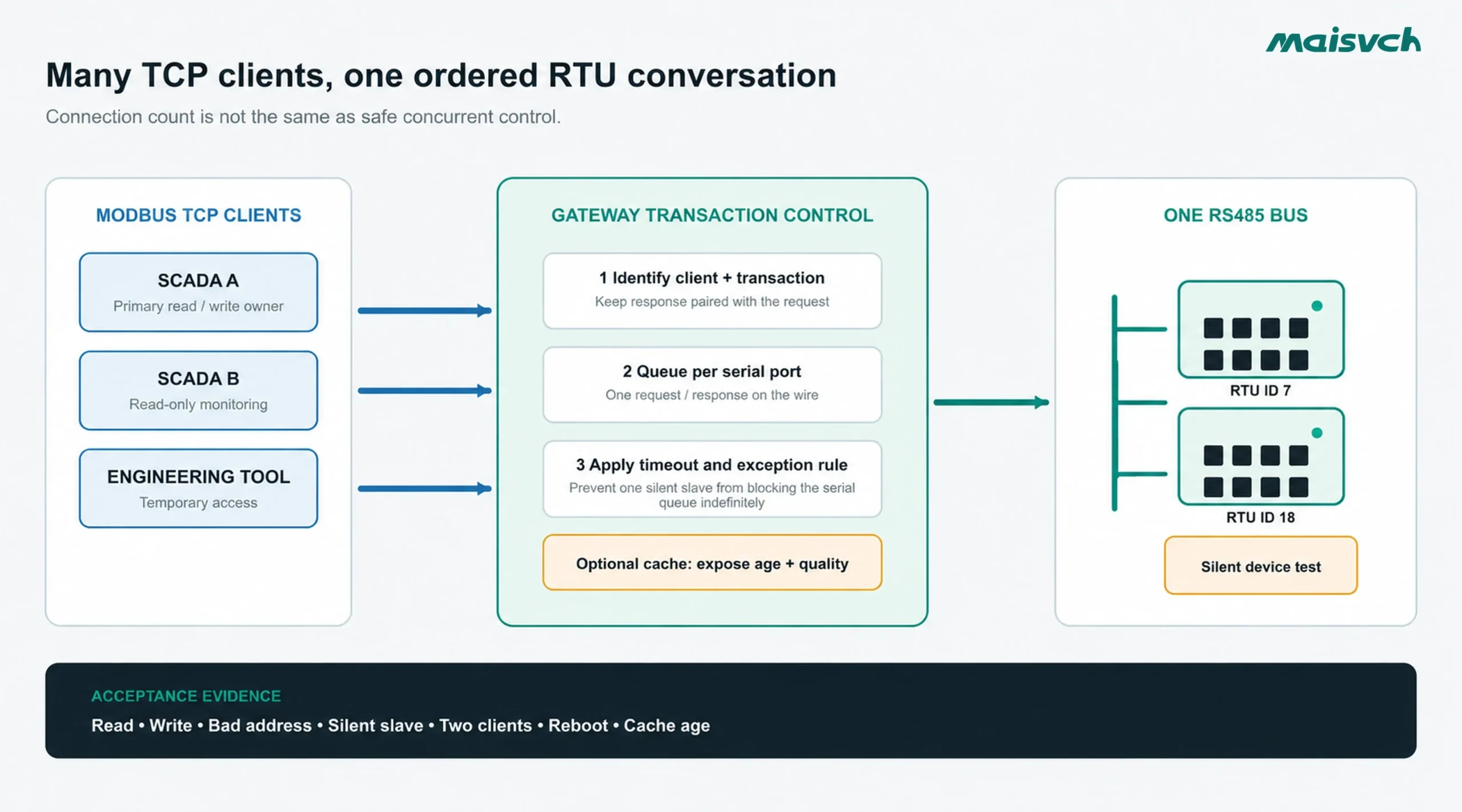
Modbus TCP can support concurrent network connections and transaction identifiers. A two-wire RS485 Modbus RTU bus still handles one request/response conversation at a time. Your gateway therefore needs a documented policy for requests arriving from different clients.
| Design question | Warum es wichtig ist |
|---|---|
| Are requests queued per serial port? | Prevents interleaved frames and gives you a way to estimate worst-case delay |
| Is there a queue limit? | A connection can remain open while requests are rejected or delayed beyond the client timeout |
| Are read and write requests treated differently? | Two independent writers can issue valid but conflicting commands |
| What happens when one slave is silent? | One long timeout can block requests to every other device on the same bus |
| Are retries performed in the gateway or client? | Duplicate retry layers can multiply traffic and delay |
| Does each client receive the correct transaction response? | Modbus TCP relies on the Transaction Identifier to pair requests and replies |
Estimate the queue before you accept a scan-time promise. If a worst-case serial transaction takes 120 ms and ten transactions are already ahead of yours, the last request cannot complete in 120 ms. It waits for the earlier work, plus any retries and silent-slave timeouts. Split heavily loaded or high-priority devices across serial ports or gateways when the resulting worst-case scan time exceeds your process requirement.
Can a Modbus Gateway Increase the Number of RS485 Devices?
A gateway can expose several addressed serial devices behind one IP endpoint and, on models with multiple serial ports, divide them across separate buses. It does not raise the electrical loading, address, cable-length or bandwidth limit of one RS485 segment. Count the transceiver unit loads, keep valid termination and biasing, and calculate the worst-case poll cycle for each serial port. If one segment exceeds its limits, split it physically; do not rely on the gateway's TCP connection count.
Unit Identifier, Address Mapping and Register Mapping Are Not the Same
The terms are often mixed together in quotations.
- Unit Identifier routing: a Modbus TCP client uses the MBAP Unit Identifier to identify the serial device behind a gateway. The official guide describes serial addresses from 1 to 247, with address 0 used for broadcast on the serial line.
- Slave address mapping: the gateway may translate one incoming unit value to a different serial device address. This is useful when two downstream segments contain overlapping addresses or the host cannot change its unit IDs.
- Register mapping: a more capable gateway may reorganize or combine register ranges. This is an application feature, not an automatic consequence of RTU-to-TCP conversion.
Ask the supplier for an example using your actual request. For example: “TCP Unit Identifier 12, function 03, starting address 400, quantity 8 must be sent to RTU server 7 without changing the PDU.” That sentence is easier to test than “supports address mapping.”
Also verify zero-based versus one-based register notation in your host software. A displayed reference such as 40001 may correspond to PDU address 0, depending on the driver. A gateway cannot correct an undocumented addressing convention reliably.
Cached Data Can Be Fast and Wrong at the Same Time
Pre-reading and caching can be valuable when several clients need the same slowly changing meter data. The gateway polls once and serves several reads without repeating every request on RS485. The engineering risk is not caching itself; it is returning an old value without a visible quality or age signal.
Define these acceptance rules before enabling cache:
- Maximum acceptable data age for each register group.
- Timestamp source and behavior after gateway restart.
- What value and status are returned before the first successful poll.
- When a device timeout changes the data to stale or bad quality.
- Whether a write is confirmed by the field device or only accepted into a queue.
- Whether mapped or combined values are updated atomically.
If the client cannot see data quality or age, use a conservative cache interval or direct-request mode for safety-relevant and command-related values. Never treat a fast response as proof that the field device was just read.
What Does Your SCADA See When One RTU Device Fails?
A transparent server typically exposes the failure as silence, a disconnected socket, incomplete bytes or a host-side timeout. Your application must decide whether the path, serial wiring or target device failed.
A Modbus gateway can provide more specific protocol feedback when the implementation supports it. The MODBUS Application Protocol Specification defines gateway exception 0x0A for an unavailable gateway path and 0x0B when the target device fails to respond. It also defines exceptions such as illegal function (0x01) and illegal data address (0x02).
Do not merely check that an error occurs. Verify that your PLC or SCADA driver exposes the distinction to operators and logs. Also record whether a silent device blocks only its own requests or delays the whole serial-port queue until its timeout and retries finish.
Five Wrong-Selection Problems That Appear During Commissioning
1. A native Modbus TCP client is connected to transparent mode
The Ethernet session opens, but the serial device never receives a valid RTU request. Correct the configured mode or use a gateway function; changing parity alone will not solve the frame mismatch.
2. RTU-over-TCP is mistaken for Modbus TCP
Modbus TCP uses an MBAP header and does not use the serial RTU CRC. An RTU-over-TCP mode may place an RTU-style address, PDU and CRC inside the TCP payload. Because implementations vary, document the exact host frame rather than writing only “Modbus over Ethernet.” Capture one successful request in hexadecimal when possible.
3. Connection count is treated as multi-master permission
Several TCP sessions reach one serial channel, and two applications poll or write independently. The result may be queue growth, timeouts or conflicting commands. Assign ownership and test concurrent clients.
4. Pre-reading hides a failed meter
The SCADA continues receiving a cached number after the field device stops responding. Without a stale flag or timestamp, the value looks healthy. Define freshness behavior before commissioning.
5. Address mapping is assumed instead of configured
The host sends Unit Identifier 5 while the downstream meter is address 17, or the driver adds a register offset. Test a known register and record the mapping table with the project backup.
Four PLC and SCADA Scenarios
Keep a legacy HMI application unchanged
Your old HMI opens a Windows COM port and already polls Modbus RTU. The field meters remain on one RS485 bus. A serial device server with a compatible Virtual COM/RealCOM driver is the simpler path. Test OS support, COM-port persistence, packetization, reconnect behavior and exclusive access.
Connect native Modbus TCP SCADA to RTU energy meters
Your SCADA driver accepts an IP address, TCP port and Unit Identifier but cannot open a serial COM port. Use a Modbus TCP-to-RTU gateway. Verify that Unit Identifier routing reaches every required RTU address and that the gateway's timeout fits both the meter response time and SCADA scan interval.
Let two supervisory systems read one RTU bus
Use a gateway that documents how it serializes multiple Modbus TCP clients, or use a supported polling/cache function when both systems can accept its data-freshness model. Give write authority to one system unless the process design explicitly coordinates writers.
Transport a proprietary RS485 protocol
If the field device does not speak Modbus, a Modbus gateway cannot infer its messages. Use a transparent serial device server and keep the protocol logic in the host application. Confirm that the server's packetization and timing preserve the proprietary protocol's message boundaries.
Run This Acceptance Test Before Full Deployment
Use the proposed hardware, firmware, field device and host driver. Save the configuration, packet capture and result sheet with the FAT record.
- Capture one valid read on both sides. Record the Modbus TCP Transaction Identifier and Unit Identifier, then confirm the RTU address, function, data and valid CRC on the serial side.
- Perform one controlled write. Confirm that the field device changed, the returned response matches the request and no second client can write without authorization.
- Request an unsupported function or address. Confirm that the expected Modbus exception reaches the host rather than becoming an unexplained timeout.
- Disconnect one RTU device. Measure how long the client waits, which exception or timeout it sees, and whether other devices on the bus remain within their scan requirement.
- Add a slow response. Check the serial response timeout, queue delay and host timeout together. Avoid retrying the same failure independently at every layer.
- Connect a second TCP client. Issue simultaneous reads, then a controlled write. Verify request ordering, transaction pairing, queue limits and read/write policy.
- Test data freshness if pre-reading is enabled. Stop the field device and record when the cached value becomes stale, how quality is exposed and what happens after a gateway reboot.
- Cycle Ethernet and cabinet power. Confirm automatic reconnection, retained mapping, known startup values and a recoverable configuration backup.
Passing a ping test or observing flashing LEDs is not an acceptance result. Your evidence should prove that the intended request reached the intended device, that the right response returned to the right client, and that failures are visible within the required time.
Match the Configured Behavior to a Maisvch Product
Maisvch offers both serial device servers Und industrial Modbus gateways. The category gives you a shortlist; the model's configured mode and verified firmware behavior decide the application.
Mport3101 when one device may need transparent or Modbus modes
Der Mport3101 serial server connects one selectable RS232, RS485 or RS422 channel to one 10/100Base-T(X) Ethernet port. Its current product page documents transparent modes including TCP Client, TCP Server, UDP, RealCOM and Pair Connection, as well as Modbus RTU/ASCII-to-Modbus TCP conversion and RTU/ASCII-over-TCP transmission.
That overlap is important: “serial server” on the product name does not mean the unit is limited to transparent transport. Select the exact mode your host requires, then run the acceptance test above. Confirm the current datasheet, firmware and ordering configuration before production approval.
Mgate3202 when you need two serial ports and gateway functions
Der Mgate3202 Modbus gateway provides two RS232/RS485 serial ports and two 10/100 Ethernet ports in a DIN-rail design. Its current product page documents RTU/ASCII-to-Modbus TCP conversion, transparent modes, Modbus slave pre-reading, address-mapping functions and serial-port isolation.
These functions are mode-specific. The page also notes that some mapping and pre-reading functions are mutually exclusive in particular modes. Put your required operating mode, mapping rule, cache behavior and client count into the RFQ, and confirm them against the current manual and sample firmware.
| Anforderung | Mport3101 starting point | Mgate3202 starting point |
|---|---|---|
| Selectable RS232/RS485/RS422 on one serial channel | Yes, as documented | No RS422 listed on the current page |
| Transparent TCP/UDP/RealCOM or pair mode | Documented | Documented |
| Modbus RTU/ASCII-to-TCP conversion | Documented | Documented |
| Two independent serial ports | NEIN | Ja |
| Documented pre-reading and address-mapping functions | Confirm exact Mport mode and manual | Documented, with mode-specific restrictions |
| DIN-rail installation and isolated serial ports | Wall-mount design; confirm the required mounting accessory or alternative model for DIN-rail installation | Documented on the current Mgate3202 page |
This table is a starting point, not a substitute for a current datasheet or project test. If isolation, surge level, temperature, cybersecurity or protocol details affect approval, put the exact requirement and test method in writing.
Copy This Modbus Traffic Profile Into Your RFQ
Host application: [PLC/SCADA/BMS/software and version]
Host-side interface: [Virtual COM / raw TCP / raw UDP / native Modbus TCP]
Field devices: [models, Modbus RTU or ASCII, RS232/RS485, device addresses]
Serial settings: [baud, data bits, parity, stop bits and wiring]
Requests: [function codes, register ranges, read/write direction and typical message rate]
Performance: [required scan time, response timeout and maximum recovery time]
Clients and authority: [number of TCP clients, one designated writer, read-only clients]
Mapping/cache: [Unit Identifier rule, address/register mapping, maximum data age and stale behavior]
Failure behavior: [silent slave, bad address, Ethernet loss, reboot and exception/log requirement]
Cabinet requirements: [power, mounting, temperature, isolation and protection]
Acceptance evidence: [two-sided packet capture, concurrency test, cache-age test and power-cycle result]
Use this profile when comparing Industrielle serielle Kommunikationsgeräte for a Modbus project. It gives an engineer enough information to recommend a mode and model, identify an unsupported requirement, and prepare a sample configuration for your bench test.