A switch can have the right port count and still be wrong for your control cabinet. The housing may fit the remaining rail space while the power terminal, SFP modules or RJ45 plugs collide with the wire duct. A nominal 24 VDC input may not cover the voltage conditions at the installed location. Two spare ports may disappear when you add a redundant uplink and a maintenance connection.
To select a DIN rail Ethernet switch, start with the cabinet and the network path–not a product list. Measure usable rail and cable space, map every endpoint and uplink, verify the actual power source, then decide whether you need management, fiber, PoE or redundancy. This guide gives you the checks, worksheet and sample tests needed to turn those conditions into a usable RFQ.
What Makes a DIN Rail Ethernet Switch Cabinet-Ready?
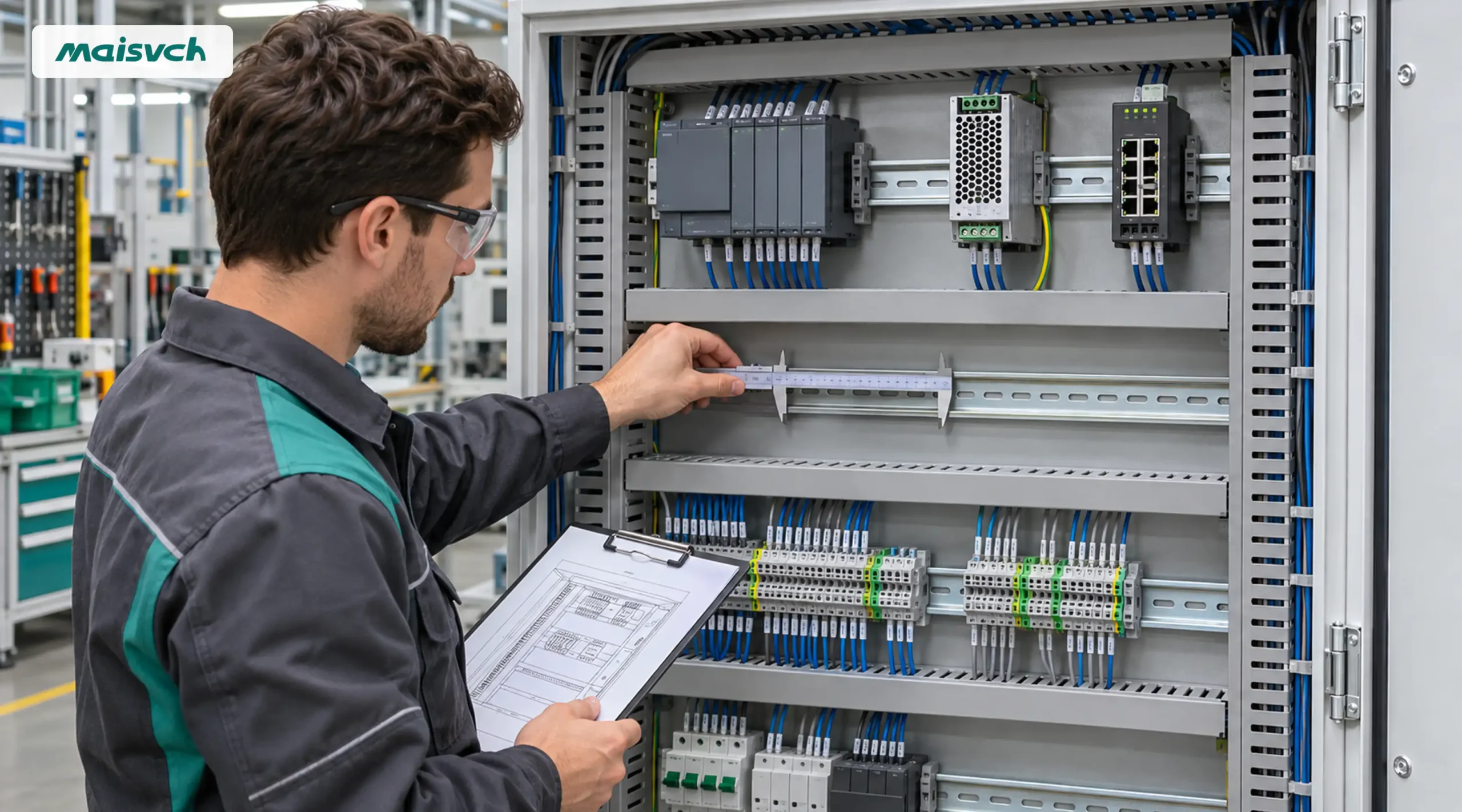
A DIN rail switch is an Ethernet switch designed to attach to a standardized mounting rail used inside control and automation enclosures. IEC 60715 defines dimensional and functional requirements for compatible mounting of low-voltage switchgear, controlgear and accessories on standardized rails. The switch datasheet must still confirm the rail type it supports; do not assume that every rail clip fits every rail profile.
Mechanical compatibility is only the first check. A cabinet-ready selection also matches:
- The usable rail width, enclosure depth and permitted mounting direction.
- The power supply voltage, current capacity, terminals and redundancy design.
- The number, speed and media type of device ports and uplinks.
- The required VLAN, diagnostics, multicast, ring or routing functions.
- The temperature, humidity, vibration, EMC and enclosure conditions.
- The project’s certificates, documentation and acceptance tests.
This is why “5-port” or “8-port” is not a complete specification. Two switches with the same port count can impose different cabinet, power and commissioning requirements.
Measure the Control Cabinet Before Comparing Switch Models
Record the six inputs below before you shortlist a DIN rail network switch. If one value is unknown, mark it for measurement or supplier confirmation instead of filling the gap with a nominal value.
| Aporte | Qué registrar | Why it changes the selection |
|---|---|---|
| Usable rail | Rail profile, free width and position of end stops | Confirms clip compatibility and whether the housing can be installed and removed. |
| Cabinet space | Usable height and depth, wire-duct position, door clearance and nearby heat sources | Prevents connectors, cables or the housing from colliding with ducts, doors or other devices. |
| Ruta del cable | Cable entry direction, connector length, bend radius, service loop and fiber-transceiver access | Determines whether ports remain usable after the switch is mounted. |
| Fuerza | Nominal voltage, minimum and maximum at the device, source capacity, fuse, grounding and redundant feeds | Separates a nominal voltage match from an electrically complete design. |
| Port map | Endpoints, copper/fiber media, speed, uplinks, ring ports, maintenance port and growth reserve | Prevents an uplink or redundancy requirement from consuming the expected spare ports. |
| Entorno | Operating temperature inside the cabinet, humidity, condensation risk, vibration, contaminants and required approvals | Defines the ratings and evidence the exact model must provide. |
Calculate rail space with the installed assembly, not housing width alone
Use the following planning expression:
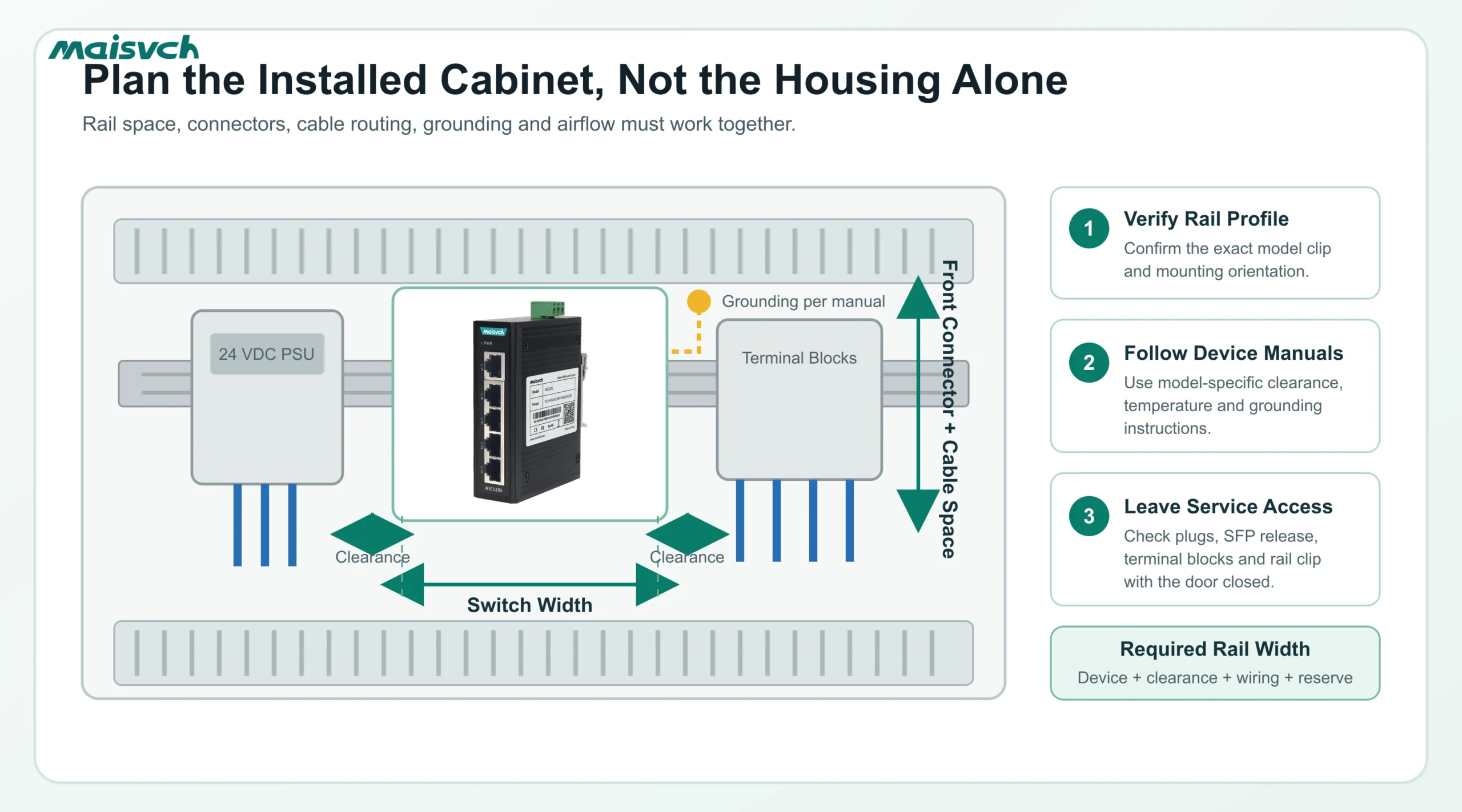
Required rail width = switch width + model-specific side clearances + wiring/service allowance + documented future reserve
The switch width comes from the current datasheet. Clearance and mounting direction come from the model’s installation manual. The wiring allowance comes from your connectors, cable diameter, bend radius, duct location and maintenance method. There is no reliable universal spacing value for every DIN rail switch, power supply and cabinet.
Also check how the unit clips onto and releases from the rail. A housing that fits between two devices may still be impossible to remove without first moving a neighboring terminal block. If your maintenance plan requires replacement without disturbing adjacent wiring, include tool and hand access in the measurement.
Check depth from the rail surface to the cabinet door
Datasheet depth may exclude the mounting clip, removable terminal block, SFP module, RJ45 plug and cable bend. Measure from the rail mounting plane to the closed door or inner panel. Repeat the check for the longest connector combination you will install.
For fiber, include the SFP body, LC connector and the cable manufacturer’s minimum bend radius. For copper, include the boot and the exit direction. The EtherNet/IP Media Planning and Installation Manual advises installing cable to the manufacturer’s bend-radius and pull-strength requirements, supporting cable to prevent damage and avoiding routes near strong electric or magnetic fields.
Do not use the switch IP code as the cabinet rating
An IP40 switch installed inside a sealed cabinet does not make the complete cabinet IP40, IP54 or NEMA Type 12. The enclosure, cable entries, cooling method and complete assembly determine environmental protection. The scope of NEMA 250 covers protection provided by electrical enclosures against specified environmental conditions and also notes that conditions such as internal condensation may require separate consideration.
Confirm the switch rating and the enclosure rating as two different items. Then evaluate internal heat, condensation and contamination under the installed operating cycle.
Build the Port Map Before Choosing a 5-, 8- or 16-Port Switch
Count connections by function, not by the number of devices visible in the first drawing.
| Port allocation | Ejemplo de pregunta |
|---|---|
| Machine endpoints | How many PLCs, HMIs, drives, remote I/O racks, meters, gateways, cameras or wireless APs connect directly? |
| Upstream connection | Is the control network connected by copper, multimode fiber or single-mode fiber? |
| Redundancia | Does the design consume a second uplink for RSTP, a vendor ring or another approved topology? |
| Commissioning | Is a local engineering or mirror port required during FAT, SAT or maintenance? |
| Approved growth | Which documented devices are expected to be added, and how many ports must remain unused? |
A cabinet with six endpoint devices may need more than an 8-port switch if two ports are assigned to redundant uplinks and one port must remain available for commissioning. Conversely, buying 16 ports for a five-device isolated cell increases rail width and power demand without solving a defined requirement.
Choose copper and fiber from the actual link path
Use RJ45 copper for compatible in-cabinet or short local links where the cable route and environment permit it. Use fiber when the distance, electrical isolation, site topology or interference environment justifies it. Your fiber specification must include speed, SFP type, wavelength, single-mode or multimode fiber, connector, optical budget and distance. “Two SFP ports” is not enough for procurement.
If the project needs several fiber drops rather than one or two uplinks, compare industrial fiber optic switches instead of forcing a copper-heavy model into the design.
Do not select every port speed from the fastest device
Many PLC and remote-I/O links generate modest traffic, but machine vision, cameras, data acquisition and upstream aggregation can change the requirement. Create a traffic path from each source to its destination, then check the busiest uplink, multicast behavior, packet size and recovery requirement. The separate guide to network switch performance explains switching capacity, forwarding rate, uplink speed and buffers in more detail.
Use 100 Mbps only where the endpoint, traffic and lifecycle requirement support it. Use Gigabit or 10 Gigabit where traffic aggregation or project standards require it. Port speed should be an engineering result, not an adjective added to every RFQ.
Verify the Power Path, Not Only the Nominal Voltage
A search for a DIN rail Ethernet switch 24VDC usually starts with the cabinet’s nominal bus voltage. Procurement still needs the exact input range and power architecture.
- Measure or calculate the minimum and maximum voltage at the switch terminals, including cable loss and supply tolerance.
- Confirm the exact model’s permitted DC or AC input range and polarity requirement.
- Confirm maximum switch consumption, not only a typical or idle value.
- Size the branch protection, terminal block, conductor and supply capacity under the project’s electrical rules.
- Define what each redundant input is expected to protect against.
- Test loss and restoration of each source on the final sample.
Dual inputs do not automatically create end-to-end redundancy
Two switch inputs fed from the same power supply and the same upstream fuse may protect against one loose terminal, but they do not protect against failure of that supply or branch circuit. If power continuity matters, document whether the two inputs use independent supplies, protection devices and distribution paths. Also confirm alarm-relay behavior and whether the switch reports loss of either input.
PoE changes both the switch and cabinet power calculation
For a DIN rail PoE switch, the supply must cover the switch itself and the required powered-device load under the specified operating condition. Confirm:
- PoE standard and required power at each powered device.
- Per-port PSE capability and total PoE budget of the exact switch model.
- Input-voltage range required to deliver that PoE output.
- Supply capacity, cable loss, ambient derating and the project’s reserve policy.
- Startup or heater load for cameras, access points and other powered devices.
Do not assume that a wide-input non-PoE model and a PoE model in the same housing accept the same power source. Confirm the order code and current datasheet.
Choose Managed or Unmanaged from the Operating Task
An unmanaged switch is appropriate when the cell uses a simple approved topology, the connected devices can tolerate the available diagnostics and no VLAN, multicast, ring or traffic-control function is required. Its value is simple commissioning, not the claim that it can never fail or require investigation.
A conmutador Ethernet industrial gestionado becomes relevant when you need one or more of the following:
- VLAN separation or controlled uplink/trunk configuration.
- RSTP/MSTP or another project-approved redundant topology.
- IGMP snooping or multicast visibility for the actual automation protocol.
- SNMP, event logs, port counters, alarms or remote status.
- Port mirroring for protocol or fault diagnosis.
- QoS, rate control, storm suppression or other documented traffic policy.
- Configuration backup and repeatable replacement-unit commissioning.
Do not pay for “managed” as a generic insurance policy. List the functions, protocol versions, limits and test cases you need. Software support varies by model and firmware.
Check Environmental and Installation Evidence Model by Model
The word “industrial” does not define one temperature range, EMC level, enclosure material or certification set. Put the required evidence in the RFQ:
- Operating temperature at the switch location inside the energized cabinet.
- Relative humidity and whether condensation is possible.
- Housing IP code and the complete cabinet/enclosure protection requirement.
- EMC immunity standards and test levels required by the project.
- Vibration and shock requirements for the machine or vehicle.
- Protective-earth or functional-ground connection instructions.
- Permitted mounting direction and ventilation/clearance requirements.
- Regional and industry approvals for the destination market.
IEC 61439-1 provides the broader service-condition, construction and verification context for low-voltage switchgear and controlgear assemblies. Your panel builder remains responsible for the complete assembly and its verification; a switch certificate does not certify the whole cabinet.
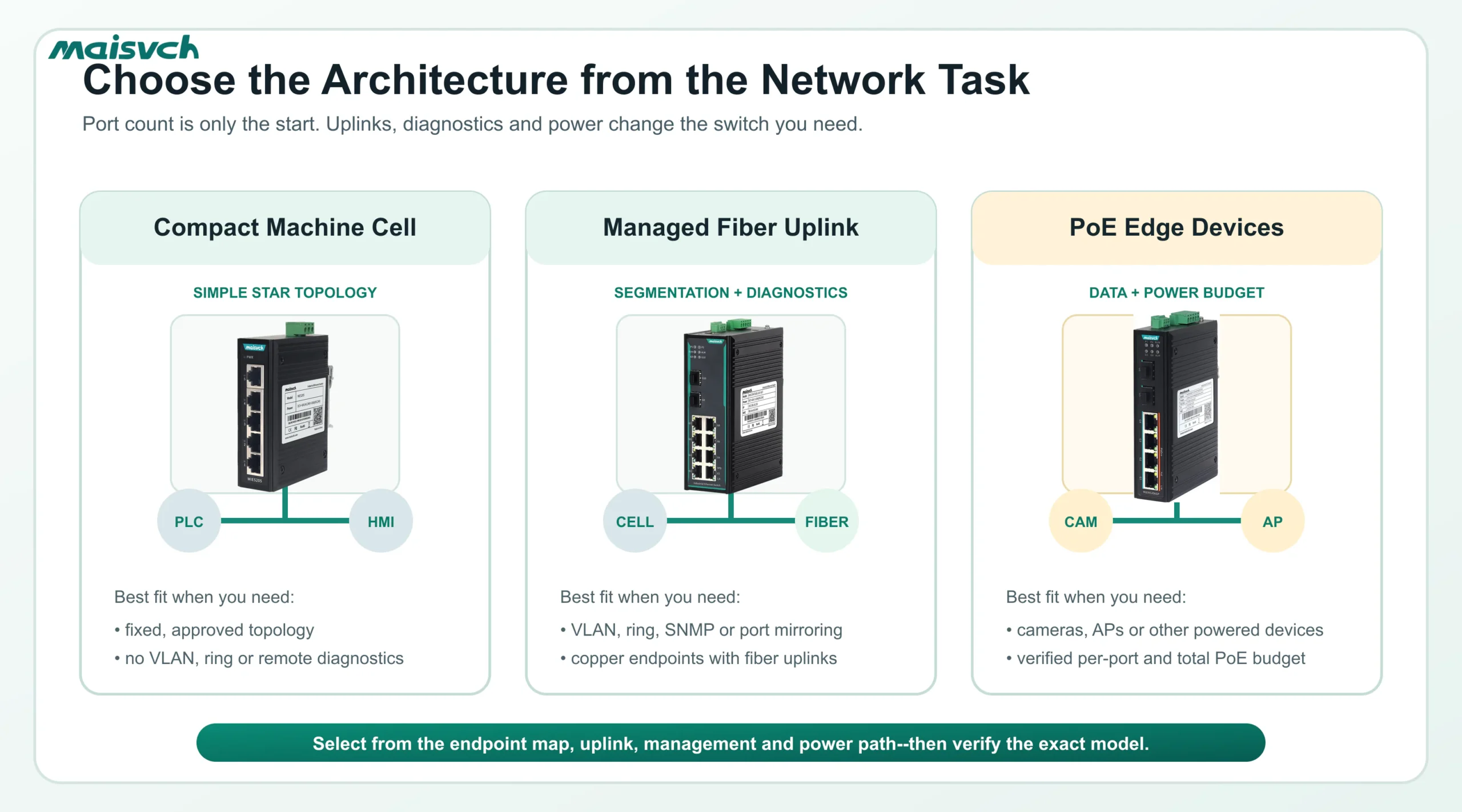
Use Verified Model Examples to Narrow the Maisvch Range
El DIN rail Ethernet switches category includes managed, unmanaged, PoE, fiber and higher-speed models. The two examples below show how cabinet inputs narrow the range; they are not interchangeable recommendations.
| Selection condition | Current model example | Verified published boundary | What you still need to confirm |
|---|---|---|---|
| Compact, unmanaged 100 Mbps cell with five copper connections | MIES205 | 5 × 10/100Base-T(X); dual DC 9–60 V or AC 24 V input; <1 W at DC 24 V full load; 102 × 33 × 78 mm excluding the DIN clip; standard 35 mm rail; -40 to +75°C; IP40. | Actual rail and connector clearance, cable route, supply/fusing, project EMC and approval needs, and whether unmanaged diagnostics are sufficient. |
| Managed Gigabit cell with eight copper devices and two fiber uplinks | MISCOM7210G-2GF-8GT | 8 × Gigabit RJ45 plus 2 × Gigabit SFP; Web/CLI/SNMP management; VLAN, IGMP snooping, RSTP/MSTP, QoS and port mirroring; DC 9–60 V model or separate AC/DC high-voltage order code; <10 W maximum; 160 × 58 × 122 mm; standard 35 mm rail; -40 to +75°C; IP40. | Exact SFPs, fiber path, ring design, firmware functions, mounting clearance, voltage order code, alarm behavior and sample configuration. |
Use current datasheets and quick-installation guides during final selection. Website data may describe more than one voltage option or model in a series; the quotation must identify the exact order code.
Copy This DIN Rail Switch Cabinet Selection Worksheet into Your RFQ
| Requisito | Project input |
|---|---|
| Application and network role | ____________________________ |
| Destination market and required approvals | ____________________________ |
| DIN rail profile and usable rail width | ____________________________ |
| Usable cabinet height and depth | ____________________________ |
| Wire duct, connector and cable-exit constraints | ____________________________ |
| Mounting direction and clearance requirement | ____________________________ |
| Endpoint list and copper/fiber speed | ____________________________ |
| Uplink and redundancy port allocation | ____________________________ |
| Maintenance and approved spare-port requirement | ____________________________ |
| Nominal, minimum and maximum input voltage | ____________________________ |
| Single or independent dual-power architecture | ____________________________ |
| PoE standard, per-port load and total budget | ____________________________ |
| Managed functions and protocol versions | ____________________________ |
| Operating temperature, humidity and contaminants | ____________________________ |
| Vibration, shock and EMC requirements | ____________________________ |
| Required documents, configuration and sample tests | ____________________________ |
Attach the cabinet drawing and endpoint topology. If your RFQ contains only “8-port industrial DIN rail switch, 24 VDC,” the supplier still has to guess the uplink, management, environmental and acceptance requirements.
Run a Sample Test Before Releasing the Panel Design
A datasheet comparison narrows the list. The sample test confirms whether the exact model, firmware, connectors and power design work in your cabinet.
- Mechanical fit: mount and remove the switch with neighboring devices installed. Close the cabinet door with final plugs, SFPs and cables connected.
- Power: test the specified minimum/maximum conditions within the approved test plan, then interrupt and restore each redundant feed separately.
- Port map: connect the intended endpoint and uplink media at the required speeds. Confirm no port is lost to an undocumented role.
- Traffic: run the expected control, multicast, camera or data-acquisition load and observe uplink utilization, errors and drops.
- Management: verify each required VLAN, SNMP, alarm, mirror, ring and configuration-backup function on the quoted firmware.
- Recovery: remove an approved link or power source and measure the behavior against the machine’s recovery requirement.
- Thermal and service access: verify the installed temperature and confirm that terminals, labels, release clips and cables remain accessible.
- Documentation: archive the order code, firmware, configuration, SFP list, wiring drawing and acceptance result.
Do not treat a successful bench ping as the acceptance test. Reproduce the cabinet, topology, power and traffic conditions that matter to the machine.
DIN Rail Ethernet Switch FAQ
What is a DIN rail Ethernet switch?
It is an Ethernet switch designed to mount on a standardized rail inside an industrial control cabinet or enclosure. Depending on the model, it may provide unmanaged or managed switching, copper or fiber ports, PoE, redundant power inputs and industrial environmental ratings. The exact rail type and mounting method must be confirmed in the model documentation.
Can you mount a normal Ethernet switch on a DIN rail?
Only if the manufacturer provides an approved DIN rail mounting method and the complete installation meets the mechanical, power, environmental and safety requirements. A generic bracket can hold a device physically without solving connector access, grounding, temperature, vibration or certification. For a production panel, select and document the intended mounting arrangement.
Does a DIN rail Ethernet switch need a separate power supply?
Most DIN rail industrial switches accept DC or, for some order codes, AC through a terminal block and therefore require a compatible external branch supply. Check the exact voltage range, maximum consumption, polarity, terminal and protective-device requirements. PoE output models may require a different input range and substantially more supply capacity.
Should you choose a managed or unmanaged DIN rail switch?
Choose unmanaged when the approved topology is simple and no VLAN, ring, multicast control, remote monitoring or detailed diagnostics are required. Choose managed when the operating task requires those functions. Write the exact feature and test case into the RFQ; “managed” alone is not specific enough.
How much spare rail space should you leave?
Use the exact switch width plus the clearances in its installation manual, the connector and cable service space, adjacent-device requirements and the project’s documented growth reserve. There is no single percentage or distance that applies to every cabinet and switch.
Can a 24 VDC cabinet power any DIN rail switch?
No. The exact model must accept the minimum and maximum voltage present at its terminals. A PoE switch may require a higher or narrower input range than a non-PoE model. Also verify source capacity, fusing, conductor size, grounding and redundant-feed architecture.
When should you use fiber uplinks?
Use fiber when the distance, interference environment, electrical isolation requirement or site topology justifies it. Specify the SFP speed, wavelength, fiber type, connector, optical budget and distance. Do not select fiber only because the switch has an unused SFP slot.
Send Cabinet Data, Not Just a Port Count
A useful switch quotation starts with the installed conditions. Send Maisvch the completed worksheet, cabinet drawing, endpoint topology, power details, environmental requirements and acceptance tests. Maisvch can then shortlist DIN rail Ethernet switches and identify which details still require confirmation on the current datasheet or sample unit.
The final choice should fit the rail, cables, power path and operating task at the same time. That is the difference between a switch that can be mounted and a switch that is ready for the control cabinet.