The PLC remains in RUN, but the HMI values freeze. A remote I/O rack drops offline for three seconds, then reconnects. The maintenance laptop can still ping the controller, yet the engineering software reports a communication timeout. These symptoms do not identify one failed component. They only show that an expected exchange did not complete.
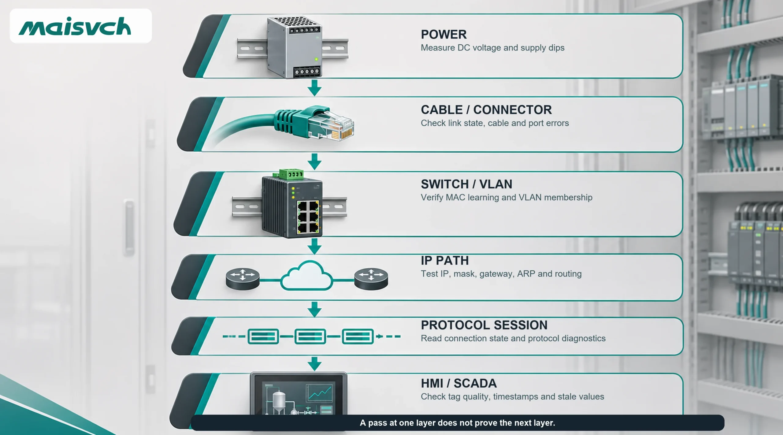
To diagnose a PLC communication failure, first preserve the evidence, then narrow the fault by scope and layer: shared power, physical media, Ethernet switching, IP configuration, protocol session and application behavior. Do not begin by replacing the PLC or increasing every timeout. The workflow below shows what to check, what each result proves and when a managed switch can provide useful evidence.

Before You Reset Anything, Preserve the PLC Fault Evidence
A power cycle may restore communication and erase the information that explains why it failed. If the process is in a safe state and the site procedure allows diagnosis, record the following before changing a cable, port or setting:
- The exact alarm text, error code and first-fault timestamp from the PLC, HMI, drive, remote I/O or SCADA system.
- The PLC mode and the state of power, run, fault, network and I/O LEDs.
- Which devices stopped updating and which devices continued to communicate.
- The switch ports involved, their link state, negotiated speed and current error or drop counters.
- Recent work: a replaced device, firmware download, IP change, new uplink, new VFD, cabinet rewiring or corporate-network connection.
- What was happening at the time: motor start, welding, recipe download, camera transfer, ring failover or loss of control power.
Export diagnostic buffers and switch logs when the equipment provides them. Take a timestamped photo of LEDs and cabling. Change one variable at a time and record the result. If the fault affects a safety function or the system is in an unsafe state, follow the machine builder’s and site’s safe-shutdown procedure rather than continuing online tests.
Scope the PLC Communication Problem in 60 Seconds
The fastest first question is not “Which device is bad?” It is “What do the failed paths have in common?”
| Observed scope | Shared dependency to check first | Useful next evidence |
|---|---|---|
| One HMI cannot reach one PLC; other devices remain normal | That device’s cable, port, IP settings, driver and PLC session | Link state, ARP/MAC entry, application error, direct test from the same VLAN |
| Several devices on one switch disappear together | Switch power, uplink, VLAN, ring path or switch hardware | Power/event logs, uplink counters, ring events, neighboring-switch logs |
| One remote I/O rack repeatedly disconnects | Rack power, local connector, device name/address and cyclic timeout | Rack voltage trend, device diagnostics, port errors and fault timestamps |
| Every device in one VLAN or cell loses communication | VLAN path, trunk/uplink, loop, broadcast storm, router or firewall policy | MAC movement, broadcast rate, topology change, interface drops and ACL logs |
| Failures occur when a VFD, contactor or welder operates | Control-voltage disturbance, grounding, shielding or electromagnetic interference | Voltage trend, cable test, error-counter trend and event correlation |
| Communication fails only after a software or equipment change | Changed IP, subnet, device name, driver, connection count, firmware or protocol setting | Configuration diff, approved backup and rollback test |
If several failed paths share a switch, power supply or uplink, test that shared point before working separately on every PLC. If only one endpoint fails while other traffic through the same infrastructure remains healthy, move closer to that endpoint and its application configuration.
PLC Communication Failure Diagnosis by Layer
Work from the lowest unverified layer upward. A successful test at one layer does not prove that the next layer works.
1. Check power and common dependencies
A PLC may stay in RUN while its communication module, remote I/O, HMI or network switch briefly loses power. Measure the voltage at the affected device under the operating condition that triggers the fault, not only at an unloaded power supply. Check redundant-input alarms, loose terminals, shared fuses, supply loading and the effect of inductive loads. If several devices restart at the same timestamp, a common power event is more plausible than simultaneous protocol misconfiguration.
Also record cabinet temperature and time-to-failure. A link that fails after several hours may point to a marginal supply, connector, transceiver or heat-sensitive module. Do not declare the PLC faulty until the power and environmental conditions at the failed component have been measured.
2. Verify cable, connector and switch-port evidence
A link LED proves that the two interfaces established a physical link at that moment. It does not prove the cable is correctly terminated, resistant to interference or stable under vibration and temperature.
Check the full path: patch lead, bulk cable, coupler, cabinet feed-through, field connector and device receptacle. Look for bent pins, corrosion, an unlocked M12 connector, crushed cable, excessive untwist, shield discontinuity and a cable routed beside motor or drive conductors. The EtherNet/IP Media Planning and Installation Manual includes planning, verification and troubleshooting guidance for copper and fiber media. Fluke Networks’ industrial Ethernet cable troubleshooting guidance explains how vibration, moisture, temperature and electromagnetic conditions can produce intermittent packet loss even when a simple continuity check passes.
On a managed switch, capture these values before moving the cable:
- Link up/down events and the negotiated speed and duplex.
- CRC/FCS errors, alignment errors and other receive errors where exposed.
- Ingress and egress drops, discards and queue-related counters.
- Port traffic rate and whether the values increase when the fault occurs.
Then move one known-good test lead or approved spare port in a controlled maintenance window. If the problem follows the cable, inspect and test the cable path. If it remains on the original device port, investigate the endpoint or port. If moving the connection changes VLAN or security policy, reproduce the original configuration first; otherwise the test introduces a second variable.
3. Check IP addressing, VLAN membership and MAC learning
For Ethernet-connected PLCs, confirm the actual settings at both ends: IP address, subnet mask, gateway where routing is required, VLAN and any device-name mechanism used by the protocol. Compare them with the approved network record, not with a remembered default.
A duplicate IP can appear intermittent because two MAC addresses answer for the same address. Check the switch MAC table and the engineering workstation’s ARP cache while the fault is present. If the MAC associated with the PLC address changes between two devices, locate both switch ports before changing an address. Also inspect DHCP or replacement-device procedures that may have introduced a factory-default or reused address.
If the PLC and HMI are in the same subnet but connected to different switches, verify that their VLAN is allowed across every trunk and that access ports are assigned correctly. If routing or a firewall sits between them, verify the required source, destination and protocol ports. NIST SP 800-82 Rev. 3 recommends documented segmentation and controlled communication paths in OT networks; a segmentation policy is useful only when the required PLC flows are also documented and tested.
4. Verify the PLC protocol session, not just IP reachability
Ping uses ICMP. Your PLC application may use TCP, UDP, raw Ethernet frames or a protocol-specific cyclic connection. A ping reply therefore confirms that an IP endpoint responded; it does not confirm that the expected PLC service is listening, that the driver is compatible or that a cyclic I/O session is healthy.
If the design question is whether a Layer 2 switch must explicitly “support” the automation protocol, use the separate guide to industrial Ethernet communication protocols. This troubleshooting section assumes that the intended protocol path was defined and now needs to be verified.
When ping works but the PLC still does not communicate, check:
- The correct engineering or SCADA driver and the expected protocol port.
- The PLC CPU/module path, slot, device name, station name, rack or Unit Identifier required by the driver.
- Connection limits and whether an old client session remained open after a network interruption.
- Firmware, project and device-description compatibility after replacement.
- Read/write permissions, tag addresses, register offsets and data types.
- The application’s response timeout, retry count and polling interval.
For PROFINET, use controller and device diagnostics rather than treating every bus fault as a switch failure. The PROFINET Commissioning Guideline notes that diagnostic information can identify module- and link-specific problems and that the underlying fault may also be in the power supply, I/O wiring, sensor or actuator.
For Modbus TCP, do not shorten the timeout until it is merely longer than a successful bench response. The Modbus TCP/IP implementation guide explains that client timeouts must account for expected transport delay and that overly aggressive retries can create additional congestion. Record the normal and worst-case response time, then set the timeout and retry policy around the application’s recovery requirement.
If the path uses RS232, RS485 or RS422, verify baud rate, data bits, parity, stop bits, address, termination, bias, polarity, signal reference and master ownership. The separate guide to RS232 frente a RS485 frente a RS422 covers those electrical boundaries in more detail.
5. Check loops, storms, multicast behavior and congested paths
A PLC packet is small, but its delivery can still be disrupted by a topology or traffic problem. Look for a newly connected redundant cable, unmanaged downstream switch, incorrect ring configuration, rapidly moving MAC addresses, very high broadcast or multicast counters, or a busy uplink that all affected devices share.
If several devices lose communication together while switch LEDs flash continuously, inspect the topology and port counters before rebooting the switches. The dedicated broadcast storm guide explains loop and storm evidence in more detail. If the fault begins when cameras, backups or machine-vision data use the same uplink, compare that traffic path with the analysis in the network switch performance guide.
For multicast-based industrial traffic, verify the required IGMP snooping and querier behavior for the actual design. For a redundant ring, check topology-change and failover timestamps. Do not enable several redundancy mechanisms on the same path without a documented design; a cable drawing that looks redundant can still create a loop or unexpected blocking state.
6. Correlate intermittent PLC communication failures with the plant process
Intermittent faults become diagnosable when network evidence shares a clock with machine events. Synchronize the PLC, HMI, SCADA and managed switches to the site’s approved time source where possible. Then compare link events, error counters and protocol alarms with VFD starts, contactor operation, welding, cabinet temperature, machine position and shift changes.
Use the correlation to choose the next test:
- Fault follows motor start: trend control voltage; inspect separation, shield continuity, bonding and cable balance.
- Fault follows machine movement: inspect flexing cable, moving connectors and vibration-sensitive terminations.
- Fault follows network expansion: check duplicate addresses, multicast/broadcast load, connection count and uplink demand.
- Fault follows firmware or project download: compare communication settings and device compatibility with the approved backup.
- Fault recovers after reboot: collect logs and session state before the next reboot; recovery does not prove the replaced or rebooted device caused the fault.
PLC Communication Failure Symptom Matrix
| Síntoma | Check first | Evidence that narrows the fault | Do not conclude yet |
|---|---|---|---|
| No link light at PLC or switch | Endpoint power, connector, cable path, disabled port and media type | Known-good cable/port test under the same configuration; optical power or cable certification where applicable | That the PLC CPU has failed |
| Link is up; ping fails | IP/subnet, VLAN, routing, duplicate IP, ACL and physical errors | ARP/MAC table, port counters, route and policy logs | That the protocol is the problem |
| Ping works; engineering software or HMI times out | Driver, service port, CPU/module path, session limit, firmware and application mapping | Protocol diagnostic, packet capture and PLC connection status | That the network is completely healthy |
| One PLC fails; other devices on the switch work | That PLC’s cable, port, address and session | Endpoint diagnostics, port errors and a controlled known-good-path test | That the shared switch is impossible as a cause |
| Several PLCs/HMIs fail at the same timestamp | Shared switch power, uplink, VLAN, ring, loop or firewall | Common event timestamps, uplink counters and topology logs | That several PLCs failed independently |
| Communication drops for seconds and returns | Power dip, loose connection, EMI, topology change, duplicate IP or retry overload | Time-correlated voltage, link events, errors, ARP/MAC changes and protocol retries | That a longer timeout fixes the cause |
| Reads work; writes fail | Permissions, PLC state, tag/register mapping, write protection and application logic | Protocol exception/status and a controlled write to a safe test point | That the cable is the likely cause |
| Fault begins after adding cameras or data collection | Shared uplink, queue drops, broadcast/multicast behavior and PLC connection load | Traffic and drop counters during the event; test without the added load in an approved window | That total switch backplane capacity rules out congestion |
What a Managed Industrial Switch Can Prove
A managed switch does not diagnose PLC logic, repair a damaged connector or translate an unsupported protocol. It can, however, preserve network evidence that an unmanaged switch cannot expose.
| Switch evidence | Question it helps answer | Boundary |
|---|---|---|
| Link events and port status | Did the physical link drop at the fault time? | A stable link does not prove error-free frames or a valid PLC session. |
| Error and discard counters | Are frames arriving corrupted or being dropped? | Counters must be sampled before and during the event; totals alone lack timing. |
| Tabla de direcciones MAC | Where is the PLC MAC learned, and does it move unexpectedly? | It does not identify an application-level duplicate or wrong tag. |
| SNMP traps, logs and alarms | Which port, power or topology event occurred first? | Time synchronization and configured destinations must be verified before the incident. |
| Storm detection and traffic statistics | Did broadcast, multicast or unknown-unicast traffic rise sharply? | A threshold alarm is not a root cause by itself. |
| Port mirroring | Did requests leave, did replies return and where did the exchange stop? | The capture point, direction and protocol interpretation must be correct. |
Configure logging, time synchronization, SNMP monitoring and any mirror port before an intermittent fault recurs. If a mirror session is required, copy only the relevant port or VLAN to an isolated analysis port and follow the site’s OT security and change-control process. Do not connect an unmanaged analysis laptop to a live control network without authorization and an approved configuration.
Use This PLC Communication Failure Worksheet
Copy this block into the maintenance ticket, FAT/SAT record or supplier support request. A complete record prevents the next person from repeating the same unproven replacements.
| Record | Project value |
|---|---|
| Fault start/end time and timezone | ____________________________ |
| Exact PLC/HMI/SCADA error and diagnostic code | ____________________________ |
| Affected and unaffected devices | ____________________________ |
| Topology and shared switch/uplink/power supply | ____________________________ |
| PLC, communication module, HMI and switch models/firmware | ____________________________ |
| Protocol and application path | ____________________________ |
| IP/subnet/VLAN or serial settings | ____________________________ |
| Link, speed/duplex, port errors and drops before/during fault | ____________________________ |
| Power voltage, temperature and concurrent plant event | ____________________________ |
| Recent change or replacement | ____________________________ |
| One controlled test performed and result | ____________________________ |
| Root cause evidence and recovery acceptance test | ____________________________ |
Write “unknown” where evidence is unavailable. Do not turn an assumption into a confirmed root cause merely because communication returned after a reboot or cable move.
Specify the Switch Diagnostics You Need Before Purchase
If the troubleshooting process shows that the current network cannot retain enough evidence, convert the gap into quotation and acceptance requirements. For managed industrial Ethernet switches, ask the supplier to confirm:
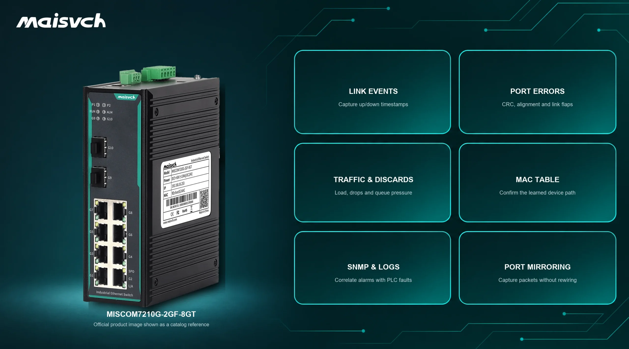
- Per-port link, speed/duplex, traffic, error and discard counters available in the web interface, CLI or SNMP.
- System logs, link/power/topology alarms, SNMP trap support and time synchronization.
- Port mirroring directions, source-port limits and behavior under the intended traffic load.
- VLAN, QoS, IGMP snooping, storm suppression/detection and loop-detection functions required by the design.
- RSTP, ERPS or the required ring protocol, including the exact topology and failure test.
- Redundant power-input and relay-alarm behavior under loss and restoration of each source.
- Configuration backup, replacement-unit restoration and firmware-management procedure.
- The operating temperature, EMC, connector, mounting and certification evidence required by the project.
Then run an acceptance test with the final model and firmware. Remove one approved link, interrupt one power input, generate a controlled diagnostic event, verify the timestamped alarm, retrieve the counters and prove that the configuration can be restored to a spare. These results are more useful than a quotation that says only “managed” or “industrial.”
Where Selected Maisvch Switches Fit
Maisvch publishes different diagnostic functions for different switch models. Match the exact order code to the evidence you need rather than assuming every managed model has the same software.
The DIN-rail MISCOM7210G-2GF-8GT page documents VLAN, QoS, rate control, IGMP snooping, storm suppression, RSTP/MSTP-compatible redundancy and port mirroring. It is a relevant starting point when a compact Gigabit access switch must expose traffic paths and support controlled segmentation.
The rack-mount MISCOM8028GX-4XGF-16GF-8GC page documents SNMP and traps, system logs, port mirroring, Ping/Traceroute, storm suppression/detection, VLAN functions, redundant-power alarms and Layer 3 functions. It is a different scale and architecture. Neither model should be selected from this article alone: confirm port media, protocol features, firmware, environmental ratings and the required diagnostic behavior on the current datasheet and sample unit.
A new switch is not the default fix for a PLC communication failure. Replace or redesign the network only after the evidence identifies a failed component, missing diagnostic capability, unsuitable environment, traffic-path limit or topology requirement.
PLC Communication Failure FAQ
How do you troubleshoot a PLC that is still in RUN?
When the task is how to troubleshoot a PLC that remains in RUN but loses network data, begin with the failed communication path rather than the CPU. Record which endpoints stopped, preserve the timestamps, check shared power and link evidence, then verify addressing and the protocol session. This separates PLC communication problems from I/O, logic and mechanical faults that need a different workflow.
Why can I ping the PLC but not communicate with it?
Ping confirms an ICMP response from an IP endpoint. The PLC driver may still use the wrong service port, CPU/module path, station name, protocol, firmware or tag/register mapping. A session limit, firewall rule or duplicate IP can also allow intermittent ping replies while the application connection fails. Check protocol diagnostics or a controlled packet capture rather than treating ping as an application test.
Can a network switch cause a PLC communication failure?
Yes, if a port, power input, uplink, VLAN, topology or traffic condition disrupts the required frames. But a switch is only one part of the path. Use link events, error/drop counters, MAC learning, logs and a controlled known-good-path test before replacing it.
Why does PLC communication fail intermittently?
Common intermittent causes include unstable control power, loose or contaminated connectors, vibration, temperature, EMI, duplicate IPs, topology changes, loops, congestion, session limits and aggressive retry timing. Correlate the exact fault time with voltage, port counters, network events and plant operation to distinguish them.
Should I increase the PLC communication timeout?
Only after measuring normal and worst-case response time and understanding the recovery requirement. A longer timeout may prevent a false alarm on a valid slow path, but it can also hide packet loss and delay fault detection. An overly short timeout with retries can add traffic and worsen congestion.
What should I send to technical support?
Send the topology, device and firmware list, protocol, IP/VLAN or serial settings, exact error text, affected/unaffected devices, timestamps, recent changes, switch logs/counters, power observations and the result of one controlled test. This is enough to choose the next diagnostic step; “the PLC goes offline sometimes” is not.
Turn the Next Failure Into a Testable Event
The useful outcome of PLC fault diagnosis is not simply restoring communication. It is identifying which layer failed, retaining evidence and proving that the corrective action survives the condition that caused the fault.
If the communication path involves an industrial switch, send Maisvch the completed worksheet with the topology, port/media plan, protocol, environmental conditions and required alarms or diagnostics. Maisvch can use those inputs to shortlist a managed switch and define the model-specific functions that still need to be confirmed during sample testing. Keep the final selection tied to measured fault evidence and an agreed acceptance test.