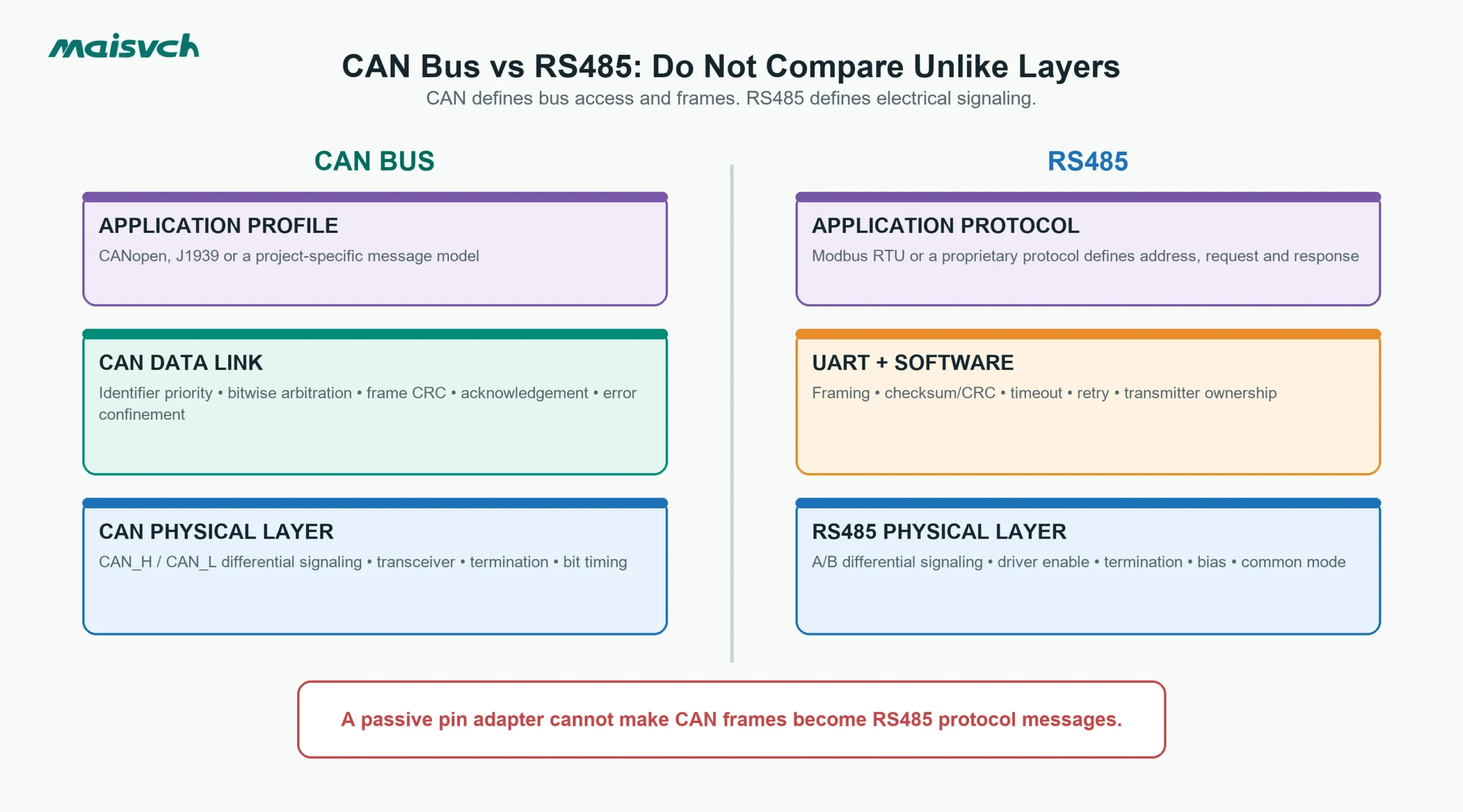
You have a controller with CAN_H and CAN_L, and a field meter with A and B terminals. Both interfaces use differential signaling, so a pin adapter may look sufficient. It is not. The CAN controller sends identified CAN frames and arbitrates bus access in hardware. An RS485 transceiver only sends and receives electrical states; the UART and application protocol define the message, address, timing and bus ownership.
That layer difference is the main answer to CAN bus vs RS485. CAN provides a standardized data-link mechanism above its physical layer. RS485 defines an electrical interface. You can choose either for a new system, but existing CAN and RS485 devices cannot communicate until a converter or gateway handles the message relationship between them.
| Decision point | CAN bus | RS485 |
|---|---|---|
| Standard scope | Physical layer plus CAN data-link behavior | Electrical physical layer |
| Bus access | Bitwise, priority-based arbitration | Controlled by the application protocol or master logic |
| Message identity | CAN identifier describes priority and message meaning | Address and function depend on Modbus or another protocol |
| Native frame/error handling | Defined CAN frames, CRC, acknowledgement and error confinement | Framing, CRC/checksum, acknowledgement and retry depend on the upper protocol |
| Typical wiring | One terminated linear trunk with short stubs | Two-wire half-duplex or four-wire full-duplex, usually a terminated trunk |
| Conversion question | CAN frames must be interpreted or mapped | Serial bytes must be framed by an application protocol |
CAN Bus vs RS485 Starts With the Standards Layer
ISO 11898-1:2024 specifies the CAN data-link layer and physical coding sublayer. It defines frame transfer, medium access, fault confinement and related CAN behavior; it does not define an application profile for your machine. Higher-layer protocols such as CANopen or J1939 add device models and message meaning.
RS485, commonly implemented from the TIA/EIA-485 electrical specification, defines balanced drivers and receivers and their electrical limits. The Texas Instruments RS-485 design guide makes the practical boundary clear: software still has to control which node transmits and must avoid bus contention in multipoint systems.
Do not describe every RS485 network as “master-slave” without naming the protocol. Modbus RTU commonly uses a client/server request-response pattern on RS485. Another RS485 application may use a proprietary token, unsolicited event messages or a point-to-point stream. Those behaviors come from the protocol, not from RS485 itself.
Arbitration Is the Largest Behavioral Difference
CAN resolves simultaneous transmission by identifier priority
CAN uses dominant and recessive bit states. During arbitration, a transmitter monitors the bus while it sends. A node that sends a recessive bit but reads a dominant bit stops transmitting; the higher-priority frame continues without being corrupted by the arbitration event. Lower numerical identifiers normally have higher priority.
This allows several CAN nodes to begin transmitting when the bus becomes idle. The identifier is not simply a device address; it normally identifies message content and also determines priority. Analog Devices’ CAN implementation guide describes CAN’s multimaster operation, message priority, arbitration, error detection and recovery.
Priority still requires engineering. A high-frequency, high-priority message can delay lower-priority traffic. Calculate worst-case bus load and response time for the messages that matter, rather than using only average utilization.
RS485 needs an upper-layer access rule
Multiple RS485 drivers can share a bus only when they do not drive conflicting states at the same time. A two-wire network therefore needs an access rule: one polling master, a token, scheduled slots or another application method.
In a Modbus RTU network, the client normally sends one addressed request and the selected server replies. In a proprietary network, the rule may be different. If two transmitters are enabled together, RS485 itself does not arbitrate the collision into a valid winning message. The result may be a corrupted frame, an electrical conflict or an intermittent fault that appears only under load.
Frames, Addresses and Error Handling Are Not Equivalent
Classical CAN uses standardized frame fields including an identifier, control information, data, CRC, acknowledgement and end-of-frame sequence. CAN controllers detect several classes of error and maintain error counters. A repeatedly faulty node can progress through error-active, error-passive and bus-off states, limiting its ability to disrupt the bus.
An RS485 transceiver sees differential voltage. It does not know whether the bytes form a valid Modbus RTU frame, ASCII line or proprietary packet. The attached UART and protocol implementation decide:
- Where a message starts and ends.
- Whether an address is a device address, broadcast or another field.
- Which checksum or CRC is used.
- Whether a reply or acknowledgement is required.
- How timeouts, retries and duplicate messages are handled.
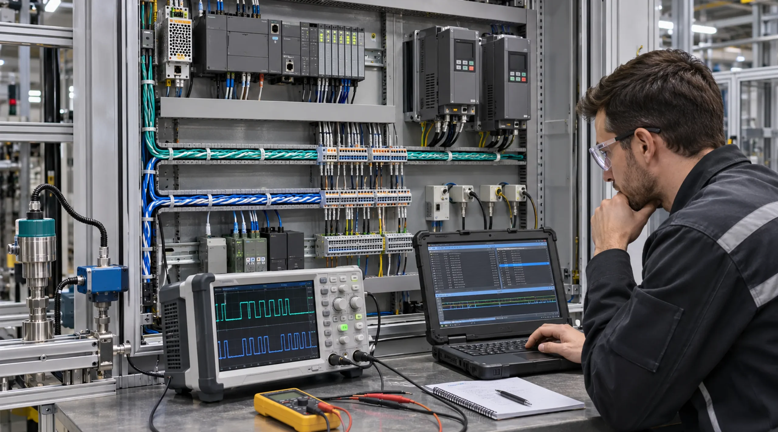
This changes diagnostics. A CAN analyzer can show identifiers, frame types and controller error states. An RS485 investigation usually needs both an electrical measurement and a protocol-aware serial capture with the correct baud, data bits, parity and stop bits.
Wiring and Termination Need Similar Discipline, Not Identical Assumptions
Both buses normally use a controlled-impedance twisted pair arranged as a linear trunk, with termination at the physical ends and short stubs. That similarity does not make their terminals interchangeable.
CAN wiring checks
- Keep CAN_H and CAN_L as a twisted pair with consistent polarity.
- Place the specified termination at the two physical ends of the trunk; many high-speed CAN networks use 120 Ω at each end, but verify the transceiver and network specification.
- Keep stubs short enough for the selected bitrate and edge rate.
- Confirm a reference/ground strategy and the transceiver’s allowed common-mode range.
- Check whether termination or isolation is built into the selected device and whether it is enabled.
RS485 wiring checks
- Confirm whether the port is two-wire half-duplex or four-wire full-duplex.
- Verify the manufacturer’s A/B polarity convention; labels are not consistently interpreted across all equipment.
- Terminate the main trunk at its physical ends when required by cable length, edge rate and topology.
- Add biasing at one controlled location when the network needs a known idle state; do not stack unknown bias networks from several devices.
- Provide a suitable signal reference or isolation when ground potentials differ.
- Avoid star branches unless the rate, cable and transceivers have been validated for that topology.
If you are choosing among serial electrical interfaces rather than comparing CAN, use the separate RS232 vs RS485 vs RS422 guide.
CAN Bus vs RS485 Distance Depends on More Than the Bus Name
There is no honest universal “maximum distance” that applies to every CAN or RS485 installation. The usable rate and length depend on cable impedance and capacitance, transceiver thresholds and edge rate, propagation delay, termination, stub length, topology, noise, isolation components and required margin.
For CAN, arbitration and bit timing require every active node to observe the bus state within the timing budget. Increasing distance and stub delay reduces the bitrate that can be used with adequate margin. For RS485, cable loss, reflections, common-mode voltage and the protocol’s response timing become limiting factors. A low baud rate alone does not repair a star topology, missing reference or out-of-range common-mode voltage.
Request the vendor’s rate-versus-distance conditions, then validate the installed cable with the real node count and worst-case environment. Do not quote a nominal distance from a comparison table as a guaranteed project limit.
Choose the Bus From the Application Behavior
CAN is a strong starting point when several controllers must publish prioritized event or control messages, deterministic arbitration matters, and the ecosystem already uses CANopen, J1939 or another defined CAN profile. The hardware-level error handling and message identifiers are useful in distributed control designs.
RS485 is a strong starting point when you need a simple, cost-effective serial physical layer, the equipment already speaks Modbus RTU or a proprietary serial protocol, and one controlled polling owner is appropriate. It also fits retrofits where thousands of existing meters, drives or instruments already expose RS485.
Do not select CAN only because an application is “real time,” and do not select RS485 only because the cable run is long. List the required message priority, node behavior, installed protocol ecosystem, diagnostic tools, bandwidth, timing and fault response.
CAN-to-RS485 Converter or Protocol Gateway?
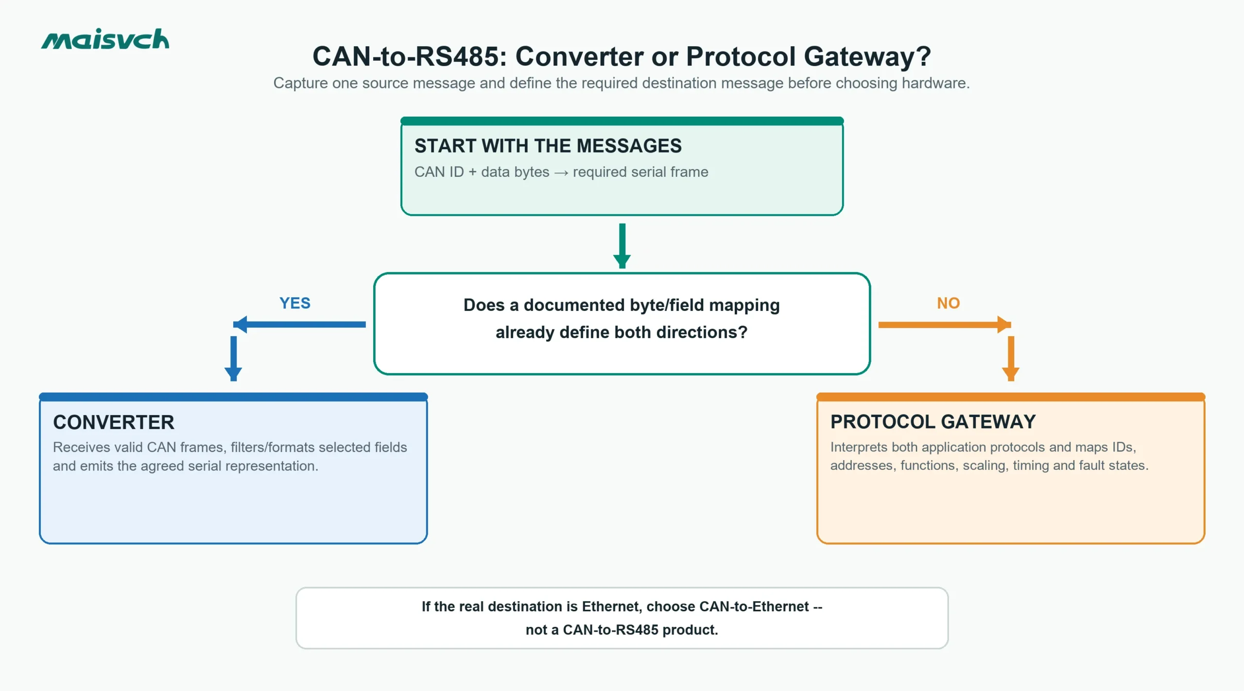
A CAN transceiver cannot be wired directly to an RS485 transceiver. The electrical thresholds, controller logic and messages differ. A useful conversion product must at least receive valid frames on one side and emit a defined representation on the other.
The remaining question is whether you need transparent data handling or application mapping.
| Project requirement | Required function |
|---|---|
| Send selected CAN frame fields as a documented serial data format | Converter with configurable formatting/filtering may be sufficient |
| Carry serial commands inside an agreed CAN-frame format at both endpoints | Converter pair or custom endpoint logic using the same mapping |
| Make a Modbus RTU meter appear as a CANopen device | Protocol gateway implementing both application protocols and object mapping |
| Map J1939 parameters to Modbus registers | Protocol gateway with J1939 decoding, register mapping and defined update/fault behavior |
| Connect a CAN network to Ethernet without RS485 | CAN-to-Ethernet device, not a CAN-to-RS485 gateway |
| Change only connector or voltage levels | Not sufficient; CAN and RS485 controllers/messages still differ |
Before selecting hardware, capture one source message and write the exact destination message. Include byte order, scaling, update rate, timeout, missing-data behavior and write direction. If no deterministic mapping exists, the converter cannot invent it.
Diagnostic Evidence to Collect on Each Side
When a converted link fails, do not change baud rates and termination at random. Prove each boundary.
On the CAN side
- CAN bitrate and sample-point settings.
- Standard 11-bit or extended 29-bit identifiers.
- Classical CAN or CAN FD requirement.
- Expected data length and one valid frame capture.
- Bus load, acknowledgement errors, error frames and bus-off events.
- Physical voltage levels, termination and stub layout.
On the RS485 side
- Two-wire or four-wire interface and verified polarity.
- Baud rate, data bits, parity and stop bits.
- Application protocol, device address and one valid request/response capture.
- Inter-frame timing, timeout and retry behavior.
- Termination, biasing, reference and isolation arrangement.
- Differential and common-mode measurements at the failing location.
At the conversion layer
- CAN identifier filters and direction.
- Byte extraction, insertion, byte order and scaling.
- Serial frame boundary and checksum generation.
- Buffer size, queueing and overload behavior.
- Update timeout, stale-data indication and reconnect behavior.
- Read-only versus bidirectional control authority.
Where Maisvch CAN Communication Products Fit
The CAN-bus converters range covers several different boundaries. Do not treat every model as interchangeable simply because it includes a CAN port.
- MW-CANET100 is a CAN-to-serial converter with one CAN interface and one selectable RS232/RS485 interface. Its documented functions include transparent, formatted and Modbus-related conversion modes, CAN identifier filtering, standard/extended frames, selectable termination and isolation. Confirm the exact frame-format or protocol-mapping mode against your source and destination messages.
- MW-CANET200 connects two CAN interfaces to 100M Ethernet and supports network modes including TCP Client, TCP Server and UDP. It is a CAN-to-Ethernet path, not evidence of CAN-to-RS485 protocol translation.
- MW-CANET300 combines CAN, serial and Ethernet interfaces. Select it only after the required data path and supported conversion mode have been verified for the project.
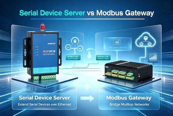
The broader industrial serial communication devices category also includes serial servers, serial-to-fiber converters, Modbus gateways and USB converters. Choose the product family from the two protocols and network boundary you actually need.
What to Put in a CAN-to-RS485 RFQ
Send enough information for the supplier to validate the conversion, not only “one CAN port and one RS485 port.”
- CAN standard/extended identifiers, bitrate and Classical CAN or CAN FD requirement.
- One representative CAN frame for every direction.
- RS485 two-wire/four-wire mode, serial format and application protocol.
- One representative serial request and response.
- Required mapping, byte order, scaling, update interval and write permissions.
- Number of nodes and expected peak message rate on both buses.
- Termination, biasing, isolation and ground-potential conditions.
- Required response when either bus is offline or data becomes stale.
- Power input, temperature, mounting and compliance requirements.
With those inputs, you can bench-test a converter or gateway against defined frames and failure states before it enters the control cabinet.
CAN Bus vs RS485 FAQ
Is CAN bus faster than RS485?
Not as a universal rule. Both are available across multiple rates, and usable rate depends on distance, cable, topology, transceivers and timing margin. Compare the required message throughput and installed-link conditions, not only a headline bitrate.
Can CAN and RS485 share the same cable?
They may use cable with similar impedance characteristics in some designs, but they cannot share conductors as interchangeable signals. Their transceivers, termination design, controller behavior and messages differ. Validate cable suitability separately from protocol compatibility.
Does RS485 support multiple masters?
RS485 can electrically connect multiple drivers, but it does not define multi-master arbitration. Multiple transmitters require an upper-layer protocol that prevents or resolves simultaneous access. Without that rule, collisions can corrupt communication.
Can a passive adapter convert CAN to RS485?
No. A working path needs active CAN and RS485 interfaces plus logic that receives one side and creates the required data on the other. If the application protocols differ, it also needs protocol-aware mapping.
Do CAN and RS485 both need 120-ohm termination?
Many high-speed CAN and RS485 trunks use termination close to the cable’s characteristic impedance, often around 120 Ω, at the physical ends. That is not a universal instruction. Verify the cable, transceiver, topology, rate and built-in termination for the specific network.